Contributor

Contributed By: Everett W. Taylor, P.E.
Title: Dam Safety Engineer
Organization: Utah Dam Safety
Email: [email protected]
Description & Background
In 1902, the Price River Irrigation Company proposed to build a dam on Gooseberry Creek about 80 miles southeast of Salt Lake City, Utah. It would be an earthfill structure with a height of 100 feet. An outlet tunnel through bedrock and a 28 feet wide by 10 feet deep spillway would facilitate releases and overflow for the reservoir.
By 1914, plans had changed. Though construction on the dam began sometime between 1908 and 1914, a submittal to the State Engineer in later 1914 indicated that the dam would now have a height of 125 feet with a concrete core wall and earthen shells on the upstream and downstream sides. Though the original design called for slopes of 3H:1V upstream and 2H:1V downstream, this new design steepened the upstream and downstream slopes to 1.55H:1V. Other design changes included a concrete outlet conduit through the maximum section with a multiple gate intake tower. Though these revised plans were submitted to the State Engineer for review and approval, the process was never completed and approval for the structure was never issued.
By the fall of 1916, construction of the core wall and upstream shell had reached a height of 67 feet. The downstream shell was 5 feet below this elevation. The crest of the dam measured 160 feet wide. Thirsty for water and with 58 feet of dam still to build, the Price River Irrigation Company made the decision to store water in the reservoir during the fall and spring of 1916-17. In anticipation of using the reservoir, 5 feet of additional core wall was placed in late fall of 1916 bringing it to a height of 72 feet. A 7 foot high earthen embankment was constructed at the upstream shoulder of the crest to provide additional storage with a 10 foot wide, 2.5 foot deep wooden flume erected to convey overflow across the crest of the dam to the right abutment and back to the stream channel. Because of the differences in elevation of the upstream and downstream shells, flow through the upper flume would drop 5 to 7 feet after passing through a rectangular notch in the core wall to a lower section of the flume. Of note is that the intake tower had only reached a height of 68 or 69 feet. To store as much water as possible, form boards were left in place providing a coffer dam around the top of the tower. As the reservoir filled, boards were nailed to the flume intake to form an 18-inch tall bulkhead. By June 24th of 1917 the reservoir level was 4 inches below the top of the wooden bulkhead.
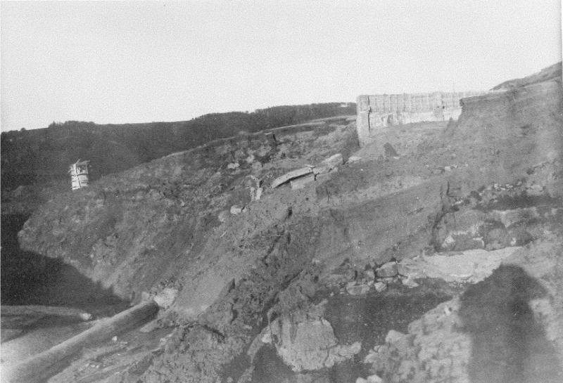
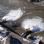
Looking upstream from the downstream toe. Note intake tower at upper left, core wall at upper right, & outlet tunnel at lower left (Photo source: the State Engineer’s Failure Report, July 1917).
On the morning of June 24, 1917, the dam watchman reported the reservoir level was holding steady or perhaps even falling slightly. With no reports of flooding and no observation of anything unusual, he retired at 11:00 A.M. to the bunkhouse, about 1,000 feet away, for lunch. When he returned the scene had changed dramatically.
At 1:00 P.M. on June 24, 1917, the watchman found that the reservoir had piped through and breached the coffer dam at the upstream shoulder of the crest and filled the space between it and the concrete core wall. Additionally, a section of the core wall approximately 5 feet tall and 30 feet wide had toppled, allowing water to spill over onto the downstream crest some 5 feet below. Fearing the worst, the watchman called for help. It is reported that the dam caretaker arrived by horseback some two hours after receiving notification. He immediately rafted out to the intake tower. Unable to operate the various gates he began to remove the form boards used to coffer the intake tower but was only partially successful. Unable to draw the reservoir down, the dam continued to overtop. As the downstream shell was washed away, the unsupported (and unreinforced) corewall continued to topple allowing more water through. The process continued until the dam had fully breached and an estimated 11,000 acre-feet of water had been released downstream.
With sufficient warning given by the watchman, no direct loss of life resulted from the failure, though it was reported one young sightseer was killed when her automobile backed into the flood. The failure did destroy the mainline of the Denver & Rio Grande Railroad Company as well as homes, bridges, highways, and other utilities and improvements. With the railroad not operating, all coal mining in the area shut down, unable to ship the coal they mined. It is reported that all the coalminers volunteered to help repair the rail line, so they could get back to work sooner. In all, an estimated $1.2 million in damage (in 1917 dollars) was caused by the failure. Mammoth Dam was never rebuilt.
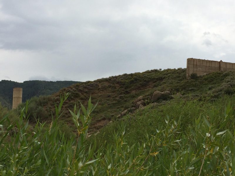
Today a smaller reservoir, Lower Gooseberry, exists about one half mile upstream of the Mammoth Dam site. You can still visit the site of Mammoth Dam and view what remains of the intake tower, core wall, and outlet conduit. In 1929, Scofield Reservoir was built several miles downstream to replace the storage lost when the Mammoth Dam project failed.
References:
(1) McGonagle, G.F. (1917). Report on the Failure of Mammoth Dam.
(2) Kleinschmidt, H.S. (1917). Defiance of Statute and Engineering Law Wrecked Mammoth Dam. Engineering News Record.
(3) McGonagle, G. F. (1919). Eleventh Biennial Report of the State Engineer to the Governor of Utah 1917-1918.
This case study summary was peer-reviewed by Douglas L. Johnson, P.E., Federal Energy Regulatory Commission.
Summary
Photos
-
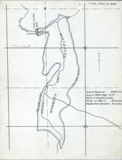
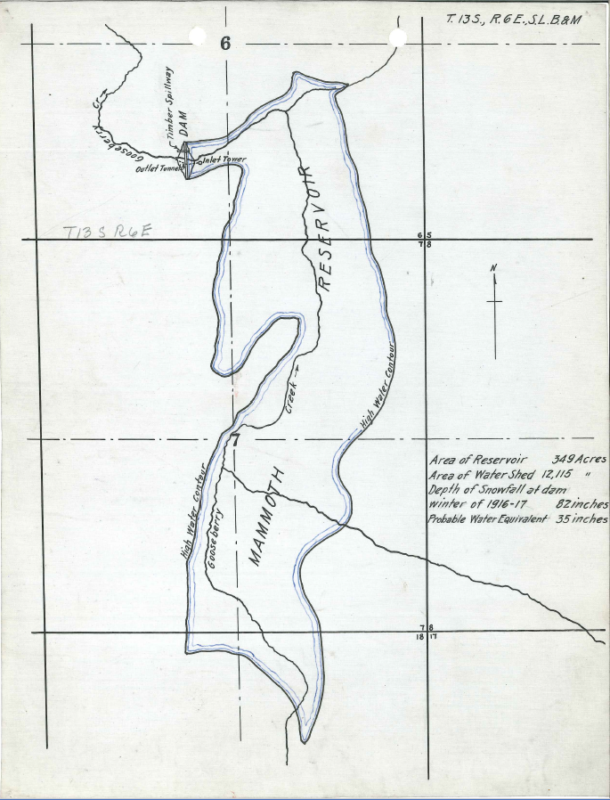
- Plan view of proposed dam and reservoir (Photo source: the State Engineer’s Failure Report, July 1917).
-
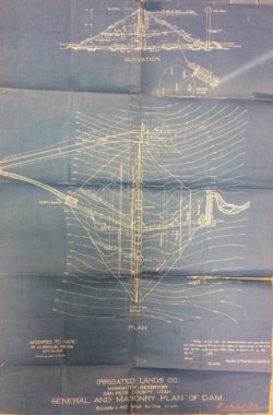
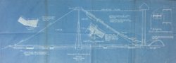
- Plan and cross section of Mammoth Dam. Unapproved by the State Engineer (Photo source: Submission to the State Engineer, 1914).

-
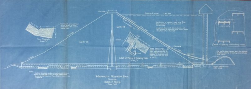
- Cross section of Mammoth Dam. Unapproved by the State Engineer (Photo source: Submission to the State Engineer, 1914).
-
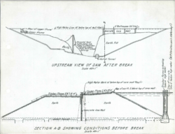
- Profile of dam after failure and cross section of the dam prior to failure (Photo source: the State Engineer’s Failure Report, July 1917).

-

- Looking upstream from the downstream toe. Note intake tower at upper left, core wall at upper right, & outlet tunnel at lower left (Photo source: the State Engineer’s Failure Report, July 1917).
-
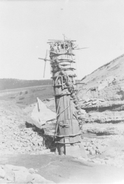
- Intake tower with formwork intact (Photo source: the State Engineer’s Failure Report, July 1917).

-
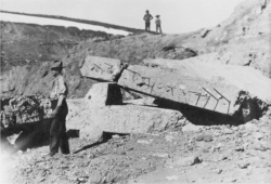
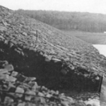
- Remnants of the concrete core wall after failure (Photo source: the State Engineer’s Failure Report, July 1917).

-

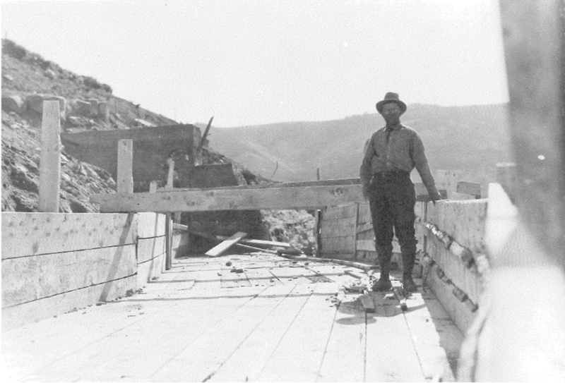
- Temporary flume spillway used to pass flows during fall 1916 and spring 1917 (Photo source: the State Engineer’s Failure Report, July 1917).
-
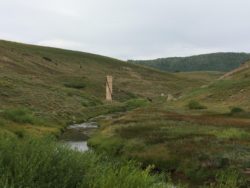
- Mammoth dam site from the reservoir basin. Note the intake structure at center and the core wall at center right (Photo source: Everett Taylor, August 2017).
-
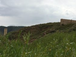
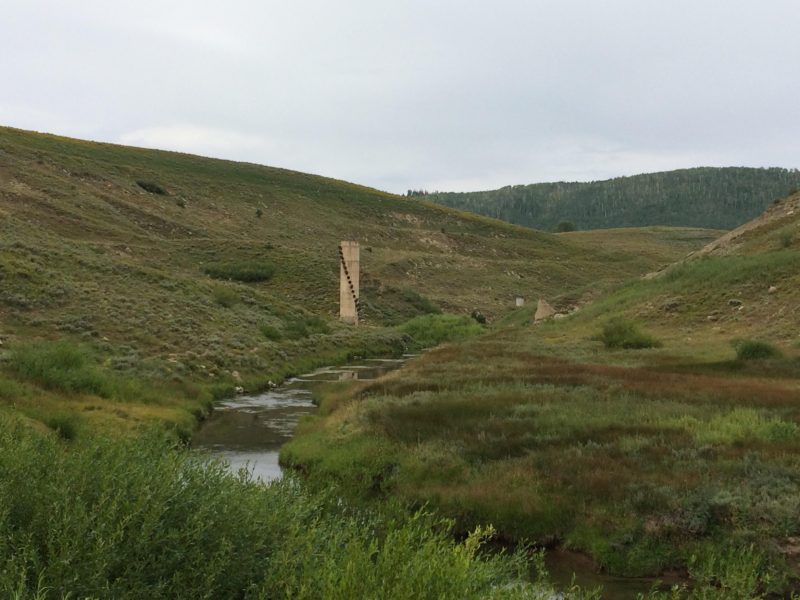
- Mammoth dam site looking upstream. Note intake tower center left and core wall at center right (Photo source: Everett Taylor, August 2017).
Videos
-

- Animation of overtopping failure developed by the Association of State Dam Safety Officials.
-
- Embankment Overtopping Bare Soil Test (MnDOT Research)
-
- Animation of piping failures at dams developed by the Association of State Dam Safety Officials.
Lessons Learned
All dams need an operable means of drawing down the reservoir.
The first filling of a reservoir should be planned, controlled, and monitored.
Additional Lessons Learned (Not Yet Developed)
- Safe operations and handling of stream flows should be considered during construction.
- Approved designs should be followed with any changes being approved prior to implementation.
Other Resources

Technical Manual: Conduits through Embankment Dams - Best Practices for Design, Construction, Problem Identification and Evaluation, Inspection, Maintenance, Renovation, and Repair.
Author: Federal Emergency Management Agency
Technical Manual published by FEMA

Technical Manual: Overtopping Protection for Dams
Author: Federal Emergency Management Agency
Eleventh Biennial Report of the State Engineer to the Governor of Utah 1917-1918
Author: G.F. McGonagle
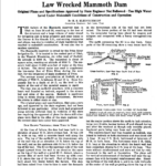
Defiance of Statute and Engineering Law Wrecked Mammoth Dam
Author: H.S. Kleinschmidt
Engineering News Record