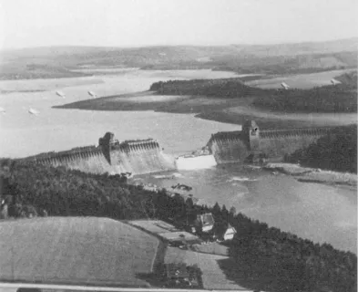
Carsington Dam failed by sliding in June 1984 and has since been rebuilt. It lies near the River Derwent, roughly 10 miles northwest of Derby, UK. The dam was first planned in the late 1960s to improve central England’s water supply. It was designed in the late 1970s to be 120 feet tall and 4,020 feet long, with an anticipated reservoir capacity of 28,400 acre-feet of water. Construction began in spring 1981 [3, 7, 9, 12].
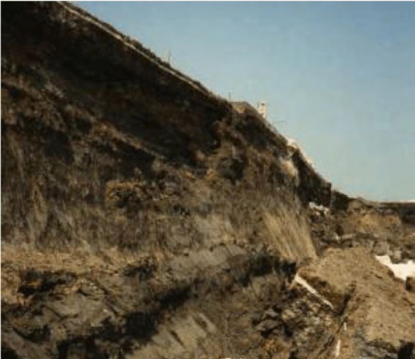
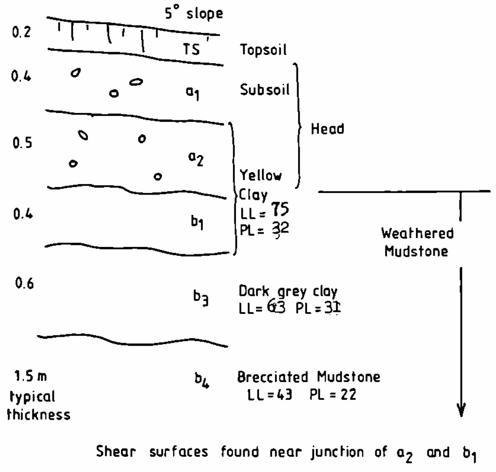
From the start, the original Carsington Dam’s geotechnical design fell far short of the standard of care. The designers generally followed the typical design of an embankment dam – clay core, inner and outer shoulders, drainage features, etc. – and incorporated some standard geotechnical features, such as grout curtains and uplift wells for seepage control. However, the team insufficiently considered several other key geotechnical factors. The site subsurface investigation found roughly 6 feet of highly plastic yellow clay beneath the topsoil, but the designers never specified that this potentially problematic material needed to be removed from the dam’s footprint. Nor did they note that the yellow clay contained shear surfaces from historical solifluction (slope creep induced by freeze-thaw cycles) at the site. The design team conducted only minimal lab testing before choosing material parameters that pushed, and in some cases overstepped, the limits of appropriate conservatism. This was especially concerning since the designers included an unconventional extended toe, called a “boot,” in the upstream side of the dam’s clay core. This boot created a region in the dam within which slip surfaces were more likely to form, but the design team did not rigorously evaluate probable slip surfaces through it. In fact, evidence suggests that critical slip surfaces within the dam were never systematically assessed. Neither, apparently, was the potential for progressive shear failure within the structure [3, 7, 9, 12].
Major issues at Carsington Dam began emerging as fill placement for the embankment got underway in summer 1982. These collectively reflected the design team’s failure to meet its responsibilities. The team failed to account for the elevated pyrite content of the mudstone clay used for the dam’s upstream shell when choosing to use limestone riprap on, and drainage blankets within, the embankment. This created the potential for sulfuric acid leaching from the mudstone clay to react with the calcium carbonate in the limestone and produce high concentrations of carbon dioxide. This tragic possibility materialized during construction when four workers were asphyxiated while inspecting a drainage tunnel in which CO2 from pyrite drainage-limestone reactions had built up. In addition, the designers had called for the dam’s core to be built of yellow clay excavated from on-site borrow pits, notwithstanding its solifluction shears [1, 3, 5, 10, 12].

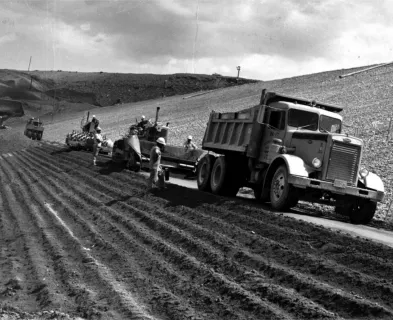
Several of the contractor’s construction decisions exacerbated the design team’s choices as construction of Carsington Dam continued. For example, the contractor placed and compacted the core and boot clay as much as 8% wet of its optimum moisture content, leading to high pore pressures and low shear strength within the already problematic material. The contractor also built a 20-foot-high toe berm extending about 785 feet along the structure’s upstream face, which allowed for quicker dam construction but reduced the already inadequate time available for the core’s oversaturated clay to consolidate. In addition, the contractor’s compaction machinery created numerous ruts within the overly wet yellow clay, each representing a potential new slip surface. Later analyses determined that these ruts most likely played only a minor role, if any, in the dam’s failure. Still, their presence reflected the cursory consideration with which all too many decisions on the project were made [3, 5, 7, 10, 12].
Despite these problems, the contractor was generally more aware of the issues at the dam than the design team and had more concerns about the project from its outset. As work progressed, the contractor became increasingly doubtful of the design’s success, especially as instrumentation installed in the dam at the designer’s instruction began indicating an incipient slope movement along its upstream face. By mid-1983, the contractor had seen enough and engaged outside engineering consultants to evaluate its concerns. The consultants reported back that fall, validating these concerns and calling attention to the designer’s insufficiently conservative parameters, improper assessment of potential slip surfaces through the boot, and alarming instrumentation data. The contractor immediately forwarded the report to the design team and attempted to meet with them to discuss both the findings and potential design modifications. However, the designers never acknowledged the report and construction continued [3, 5, 12].
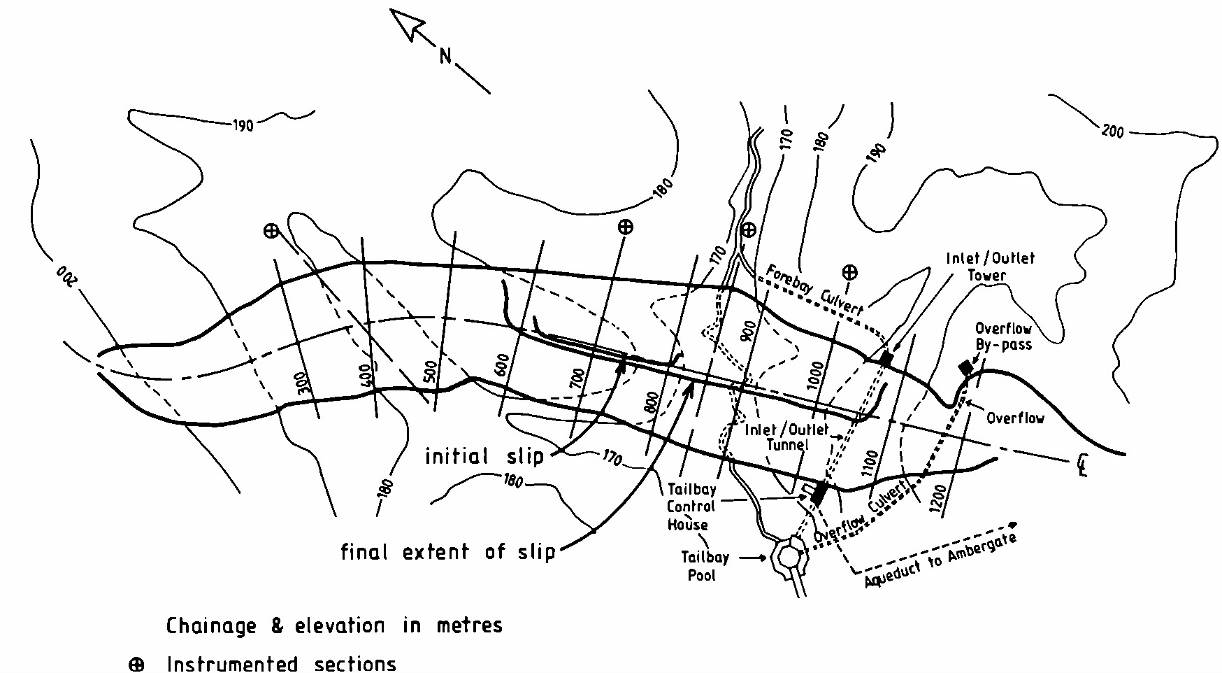
The problems remained, though, and work at Carsington Dam soon came to an abrupt halt. The earliest sign of imminent trouble came in late May 1984, when a section of the dam’s upstream face near the eventual slide location moved about 2 inches laterally in just a week. The first weekend of June likely worsened the emerging issues, as approximately 1.6 inches of rain fell. When the contractor’s crews returned to the jobsite on Monday, June 4th, they discovered that the toe of a 395-foot stretch of the dam’s upstream face now exhibited as much as 3 to 4 inches of additional lateral displacement. Moreover, a head scarp crack up to 2 inches wide had formed in this region. The crews began an emergency expansion of the upstream toe berm right away, hoping to stop the slide, but the problem quickly worsened, and their hard work proved fruitless. By Monday evening, the crack was as much as 5 inches wide. The next morning, it had grown up to 14 inches wide and was getting longer. By Tuesday afternoon, as the crews continued toiling on the berm, the crack was widening as much as 6 inches per hour; by that evening, it extended along 1,540 feet of the dam, and portions of the upstream toe exhibited up to 8 feet of lateral displacement. Even larger movements occurred overnight from Tuesday to Wednesday. When the slope finally stopped sliding on Thursday, June 7th, the failure had a lateral extent of roughly 1,625 feet. The dam’s upstream slope had undergone up to 43 feet of lateral displacement, and its crest had slid downward as much as 33 feet [8, 11, 12].
Since Carsington Dam was still under construction, its failure fortunately led to neither flooding nor human casualties. Still, the subsequent investigation and rebuilding process was – like any other – long and expensive. The post-slide geotechnical forensic investigation and failure analyses constituted a noteworthy achievement in dam engineering. The client, designer, contractor, and forensic engineers were all eager to get to the root of what had happened, and the investigation was therefore an unusually cooperative effort. “A remarkable degree of unanimity existed among the [investigative] committee members,” one geotechnical engineer involved noted. The forensic site work included a thorough regimen of sampling and laboratory testing, along with an extensive battery of CPT probes. The hazards overlooked in design reappeared when some test pits had to be ventilated before sampling due to excessive carbon dioxide from the pyrite drainage-limestone reactions. Meanwhile, the analyses used finite element models to successfully establish that progressive failure had occurred. This represented a major advance for the dam engineering profession, in which FEM for forensic investigations was still coming into common use [6, 7].
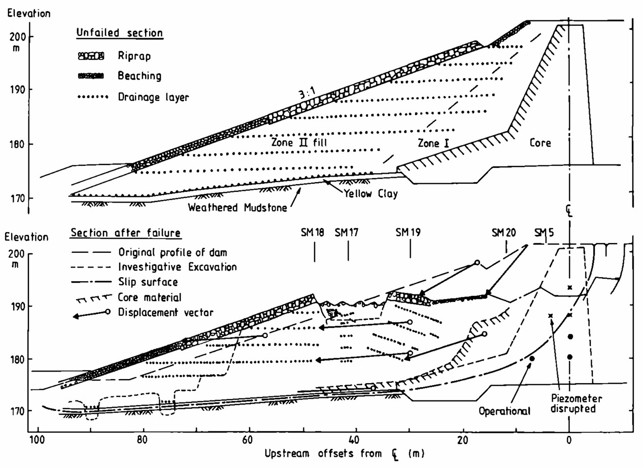
The forensic engineers concluded that the Carsington Dam slide stemmed primarily from a combination of the factors described above. The eventual slip surface had extended through the core boot’s yellow clay, as well as the thin stratum of it left in place beneath the dam. The clay was brittle, a geotechnical phenomenon not yet widely recognized in 1984, so the core had undergone non-uniform strain and had failed progressively. Thus, the exclusive use of peak or even fully softened shear strength parameters in design without considering residual strength had been erroneous. Eventually, the combination of progressive failure and solifluction surfaces within the yellow clay in both the core and the native stratum left beneath the dam had lowered the factor of safety for slope stability at the initial point of failure to 1, resulting in the slide. As the failure played out, lateral load transfer shifted forces from the failed portion of the dam onto adjacent portions, reducing their already low FS values to 1 and propagating the failure outward. The FEM work also showed that the contractor’s construction of a buttress berm along the dam’s upstream toe had increased the FS of the marginally stable slope far less than limit equilibrium-based calculations had predicted [3, 7, 12, 13].
The civil engineers who analyzed the Carsington Dam slide emphasized that reconstructing the dam would require better choices of design parameters, more consideration of the possibility of progressive failure and probable slip surfaces, and – perhaps most importantly – receptiveness by the designers to concerns from the contractor and/or outside consulting engineers. The disaster made clear the importance of recognizing the brittle nature of some clays, considering progressive failure in dam design, and using FEM in these designs to assess slope stability. The failure prompted years of vigorous and productive discussion in the British dam engineering community about the nature and proper modeling of progressive failure in clays. Geotechnical practitioner A.D.M. Penman spoke for everyone involved in these discussions when he wrote, “We must always be grateful for the opportunity to analyze failure – without failure we know less about the actual mechanisms of failure” [5].

Design of the new Carsington Dam began almost as soon as the forensic investigators released their findings. The new design team added several features to the rebuilt dam to ensure its success. The new, more geotechnically rigorous design utilized more conservative material parameters that reflected an improved understanding of progressive failures. The designers eliminated the core boot and limestone drainage blankets, instead opting for a downstream filter drain. They significantly reduced the embankment’s slopes from 3:1 (H:V) to 3.5:1 along its upstream face and from 2.5:1 to 3:1 along its downstream face and added berm-like steps along both faces for additional stability. The designers also used FEM analyses to confirm the new design’s robustness. During construction, the designers and contractors used an extensive instrumentation program to check that observed and predicted soil behavior were congruent, as they proved to be. They also implemented strict protocols to prevent machine-induced rutting shear surfaces in the clay core, such as forbidding construction equipment from driving across completed fill areas before subsequent fill layers were placed. The job was further complicated by the need to remove over 2.6 million CY of failed material from the original dam during construction of the new dam. Despite these constraints, the contractors completed the new Carsington Dam in October 1991, 12 months ahead of schedule. It has performed satisfactorily ever since [2, 4, 7, 9].
The Carsington Dam failure remains a powerful teaching tool for dam engineers over 40 years after it happened. However, it has been covered far more extensively in UK technical literature than in American engineering publications. Hopefully, US dam and geotechnical engineers can use the Carsington failure to help prevent similar or worse such disasters at American dams.
References:
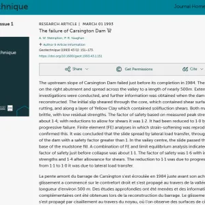
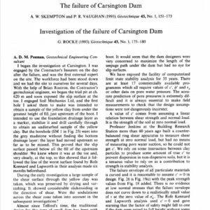
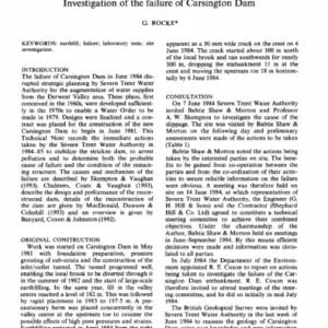
(7) Rocke, G. (1993). Investigation of the failure of Carsington Dam. Géotechnique, 43(1), 175-180.
This case study was peer-reviewed by Jerry Pascoe, P.E., G.E. (Slate Geotechnical Consultants, Inc.).


Lessons Learned

Dam incidents and failures can fundamentally be attributed to human factors.
Learn more
Earth and rockfill embankment dams must be stable under the full range of anticipated loading conditions.
Learn more
Forensic investigations are needed for major dam failures and incidents in order to determine the history of the contributing physical and human factors, and the culminating physical failure modes and mechanisms.
Learn more
Stability of the dam foundation and other geologic features must be considered during dam design.
Learn more
The study of past incidents and failures aids in the assessment of existing dams.
Learn moreAdditional Lessons Learned (Not Yet Developed)
- Mineralogy and depositional history of dam construction materials must be considered and evaluated.
- Non-standard dam designs must be rigorously analyzed for common failure mechanisms.
- Progressive geotechnical failure must be considered in dam designs, preferably using finite element methods.