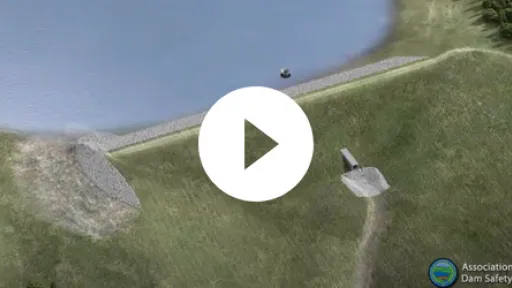
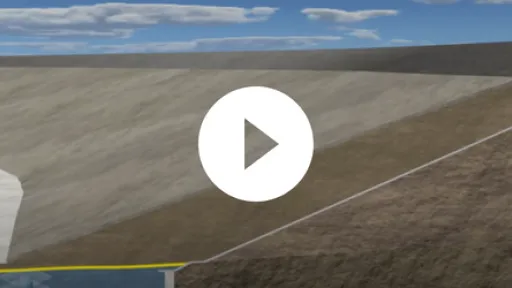
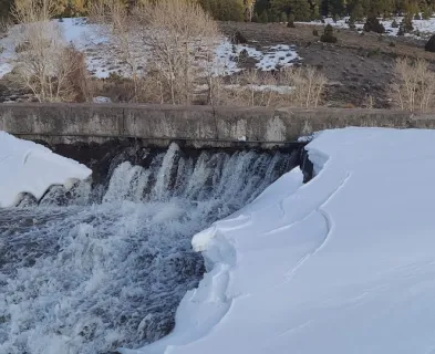
Earth and rockfill embankment dams must be stable under the full range of anticipated loading conditions.
According to the Association of State Dam Safety Officials (ASDSO), foundation defects and slope instability are among the top five most common causes of dam failures, responsible for about 30 percent of all dam failures. [1] While this statistic alone highlights the importance of verifying embankment dam stability, anecdotal evidence suggests that the frequency of slope instability incidents may be much higher. Slope instability incidents are often left unreported because they are detected early and intervention is successful.
“Foundation defects, including settlement and slope instability, cause about 30% of all dam failures.”
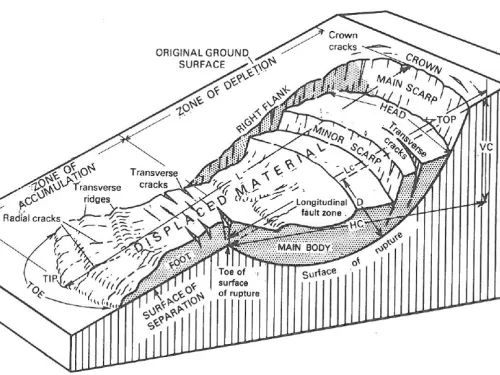
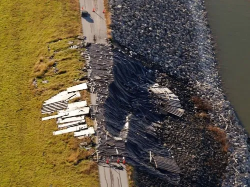
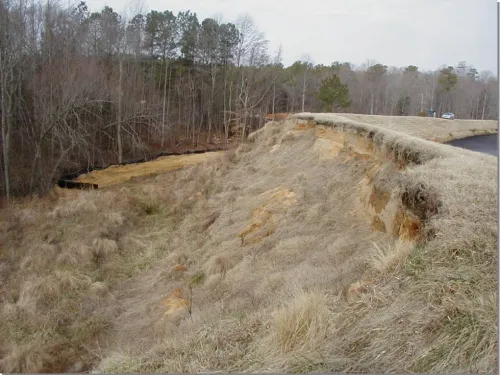
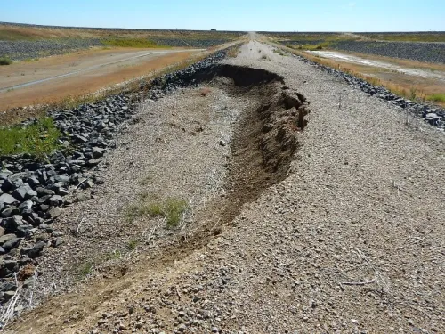
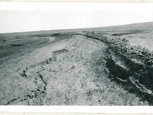
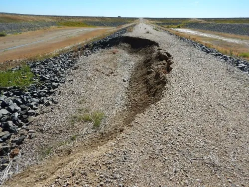
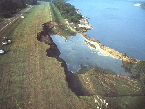
In general terms, embankment dam instability occurs when a load or force is exerted on soil that exceeds the soil’s ability to resist the load. Slope instability typically takes the form of a circular- or wedge-shaped failure on one of the slopes, commonly referred to as a “slide” or “slump”. A slope failure is a significant dam safety concern because it is an initiating event that can develop with little warning and very quickly progress to a complete dam failure and/or immediate life loss when slope failures occur during construction. Slope failures can happen quickly or slowly, on the upstream or downstream slopes, and occasionally along the reservoir rim depending on the type of material and conditions applied. Slope failures can result from external forces such as earthquakes, internal forces such as elevated pore pressures, and human-induced events such as the removal of soil at the toe of a slope during construction. Slope failures can be the singular cause of a dam failure, or can be one step in an event chain that ultimately leads to a dam failure. Examples of commonly considered failure modes associated with slope instability include:
- A downstream slope failure surface extends fully through the dam and intersects the reservoir, initiating an overtopping dam failure.
- A downstream slope failure mobilizes enough soil to expose the saturated zone below the phreatic surface within a dam, initiating seepage that leads to a dam failure.
- An upstream slope fails during a rapid drawdown of the reservoir and plugs or damages the outlet works. Without a means to drawdown the reservoir, the reservoir rises and overtops the dam at the location of the upstream slope failure.
In order to design a stable dam, engineers must first have a thorough understanding of the existing site conditions. This typically involves an extensive literature review and one or more geotechnical site investigations. Next, the engineers must identify the loading conditions to which a dam will be exposed that could lead to slope instability. Through this process, engineers can identify critical geotechnical considerations and incorporate defensive design measures to counteract adverse conditions.
Engineers have historically incorporated multipliers, or factors of safety, when evaluating the ability of the dam to resist anticipated loading conditions. Factors of safety provide a buffer to account for potentially unidentified adverse conditions. Factors of safety generally vary in scale based on the frequency of occurrence, but can also reflect the engineer’s confidence in the analysis results. Loading conditions that occur relatively frequently, such as steady-state seepage during a full reservoir, are typically assigned a relatively high factor of safety multiplier. Less frequent loading conditions such as steady-state seepage during flooding, rapid reservoir drawdown, temporarily over-steepened construction slopes, and post-construction excess pore pressures are assigned a slightly lower factor of safety multiplier. Extremely infrequent conditions such as dynamic earthquake loading are assigned a very small factor of safety multiplier, if any.
The factor of safety based evaluation method is still relatively common, particularly for the design of small dams; however, an alternative methodology has been introduced and is gradually becoming more commonplace. The essence of the risk evaluation is to reduce and/or replace the rather ambiguous factors of safety with a more precise measure of the anticipated frequency of occurrence and confidence level. The ultimate intent is to identify the risk driving potential failure modes and include appropriate defensive design measures into the design. Regardless of the selected evaluation methodology, the key to a successful design is to have a team of highly experienced engineers who understand the specific site conditions and the type of dam under design.
Modern technology and published research proclaiming new correlations for estimating soil and rock strength parameters have made it very easy to develop computer-aided stability models and generate results. In addition, the pressure applied to consultants to deliver projects under budget creates the temptation to rely on published correlations to derive input parameters. Unfortunately, results are only as good as the input, and reliance on generalizations about a poorly-known soil material, or limiting slope stability evaluations to those commonly published cases without consideration for the site specific characteristics, can be disastrous. Significant expertise and understanding of geologic and geotechnical engineering, site investigations, and laboratory testing are often necessary to generate reliable input parameters for stability analyses and truly understand the conditions that could lead to dam instability. Except for very small dams where it may be more economical to design a dam with highly conservative slopes, the geotechnical aspects of dam design and construction should not be ignored or taken lightly.
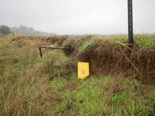
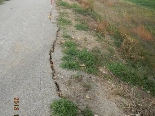
Slope instability incidents can have significant economic and emotional effects, even though they may not lead to complete dam failure and loss of reservoir contents. For example, longitudinal cracking along a dam crest coupled with vertical offset across the crack is common enough to initiate intervention to prevent the condition from developing into a complete dam failure. Intervention often includes engineering evaluations to determine the root cause of the problem followed by construction of repairs and modifications to prevent the problem from recurring. While dam safety incidents may not result in a dam failure, the subsequent intervention can create an economic drag on the owner and/or tax payers, may delay construction of other projects, and could have otherwise been avoided.
While there are very few, if any, reported cases of rockfill dam instability to date, it would be naïve to presume that all rockfill dams are immune to instability; therefore stability analyses should be conducted on rockfill dams to the same degree as is done for soil embankments. Assuming both upstream and downstream slopes of a rockfill dam are stable, additional consideration must be given to the stability of the foundation, core, upstream facing (if any), and the interface between the dam and foundation. More information about foundation defects and the interaction between dams and their foundations is discussed in the companion lesson: “Stability of the dam foundation and other geologic features must be considered during dam design.”
Embankment and rockfill dam stability is a critical and highly complex component of safe dam design. We are fortunate to have a wide array of tools and published research to aid in slope stability evaluation; however, the extensive readily available resources can also be a double edged sword when not fully understood. More than anything else, it is absolutely critical that the design engineer understands the geotechnical aspects of the existing site and proposed dam to minimize the chance that a key design component is misinterpreted or overlooked.
References:
(1) ASDSO. (2018). Dam Failures and Incidents. Association of State Dam Safety Officials.
This lesson learned was peer-reviewed by Everett W. Taylor, Utah Division of Water Rights.
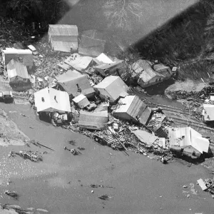
Buffalo Creek Dam (West Virginia, 1972)
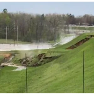
Edenville Dam (Michigan, 2020)
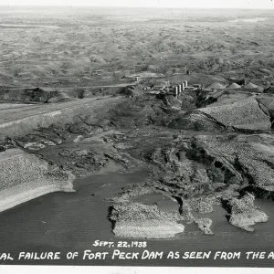
Fort Peck Dam (Montana, 1938)
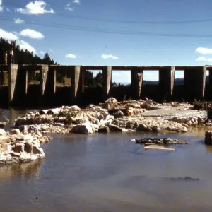
Hebgen Dam (Montana, 1959)
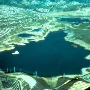
Lower San Fernando Dam (California, 1971)
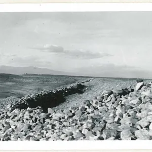
Marshall Lake Dam (Colorado)

New Orleans Levee System (Louisiana, 2005)

Prospect Dam (Colorado, 1980)
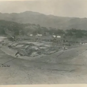
Sheffield Dam (California, 1925)

South Fork Dam (Pennsylvania, 1889)
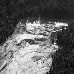
Val di Stava Dam (Italy, 1985)
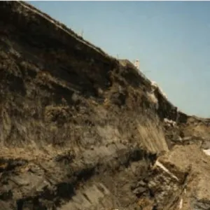
Carsington Dam (United Kingdom, 1984)
Additional Case Studies (Not Yet Developed)
- Lewisville Lake Dam (Texas, 2015)
- Certej Tailings Dam (Romania, 1971)
- Mississippi River Levee (Louisiana, 1983)
- Woman Creek Dam (Colorado, 2013)
- Baseline Dam (Colorado, 2013)

Federal Guidelines for Dam Safety: Earthquake Analyses and Design of Dams
Training Aids for Dam Safety: Evaluation of Embankment Dam Stability and Deformation

Training Aids for Dam Safety: Inspection of Embankment Dams
Best Practices - Embankment Slope Instability

Best Practices - Probability Stability Analysis

Design Standards No. 13: Embankment Dams - Chapter 2
Design Standards No. 13: Embankment Dams - Chapter 4
Design Standards No. 13: Embankment Dams - Chapter 9

General Design and Construction Considerations for Earth and Rock-Fill Dams, EM 1110-2-2300


Western Dam Engineering Technical Note: Volume 1, Issue 3

Western Dam Engineering Technical Note: Volume 2, Issue 2

Western Dam Engineering Technical Note: Volume 2, Issue 3

