Description & Background
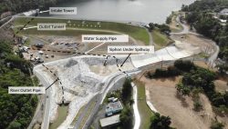
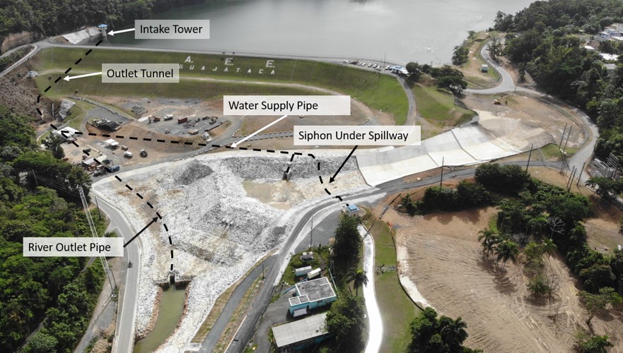
Guajataca Dam is a 121 foot high, 1,037 foot long, high hazard potential earthen embankment structure constructed using semi-hydraulic fill methods for the central core (i.e., puddle core) and rolled and compacted outer shells composed of a mixture of clayey soils, gravel, and cobbles. The facility has a low-level outlet works control structure and conduit through a right abutment tunnel; an uncontrolled semicircular concrete weir spillway with an approximately 700 foot long trapezoidal-shaped concrete chute discharging back into the Rio Guajataca; and a 54-inch diameter water supply line that empties into an open channel canal after flowing through a siphon buried under the spillway.
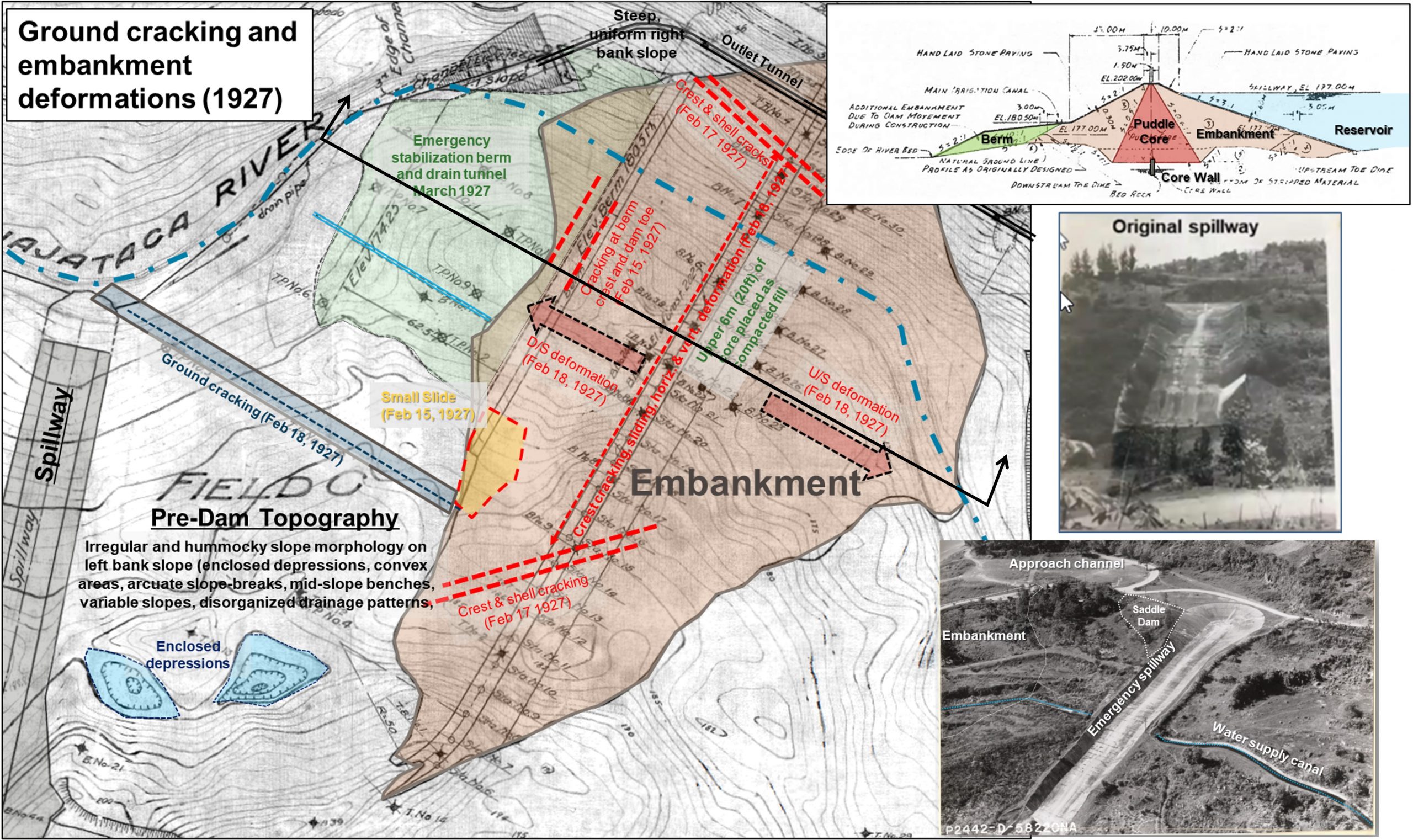
The spillway and majority of the dam foundation that are positioned on the left side of the Rio Guajataca and are founded on a large (0.25-0.5 mile wide by 2 miles long), deep-seated, and actively deforming translational landslide complex, which in conjunction with the semi-hydraulic core fill construction method, contributed to significant deformations of the embankment and surficial ground cracking that occurred during initial construction (1927). Over the following decades the landslide and project structures to the left of the river continued to creep and shift resulting in significant cracking and deformation (e.g., settlement, lateral movement, rotation, etc.) within the spillway monoliths, chute slabs, training walls, and within the embankment itself.
In the late 1970’s to early 1980’s an engineering analysis and design was implemented to evaluate and repair damaged portions of the spillway structure consisting of replacement of distressed slabs along the lower portion of the chute and adding a cutoff wall at the weir crest. The design also included reinforcement of the embankment with a stabilization berm and filters. Repairs to the spillway included articulating chute slabs on neoprene that would allow differential movements without structural damage to the spillway. Construction activities and placement of the stabilization berm triggered additional movements of both the embankment and landslide foundation. The construction solution was to replace the open channel outlet works with a buried 96-inch diameter pipe outlet pipe along the river channel and then place a compacted earth structural buttress at the dam toe that extends across the river. Based on available instrumentation data this stabilization measure did appear to slow the landslide movements, but additional creep continued (measured as a few millimeters per year) within the foundation landslide mass.
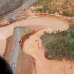
PREPA project files & USACE aerial photo of damaged spillway. (Photo Source: U.S. Army Corps of Engineers, 2017)
The spillway is aligned sub-parallel to the direction of movement of the landslide mass, and it discharges orthogonally back into the river, forcing spillway flows to make a nearly 90-degree turn at the bottom of the chute. The chute included 18-inch-high steps (i.e., drops) between the articulating chute slabs (intended to accommodate shifting due to continued landslide creep). The only energy dissipation was placement of rip rap at the lower portion of the spillway chute and no baffle blocks or stilling basin were included in the re-construction. Beyond the end of the spillway the in-situ foundation materials at the downstream end of the chute and riprap had limited erosion or scour protection and the materials were found to be composed of previously disturbed and weakened landslide materials. Following the 1980’s reconstruction continued foundation re-adjustments and displacement related to the creeping landslide movements manifest as cracking, settlement, and distortion of the spillway slabs and walls. During this deformation, binding of the articulated spillway slabs caused increased stress and significant cracking, wall rotation, and formation of foundation voids over the past 40 years of service. During this time, it’s considered likely that precipitation and subsequent spillway flow events infiltrated through the cracks and potentially caused erosion and deterioration of the underlying foundation materials and/or plugged or damaged the underdrain system.
Hurricane Maria made landfall over Puerto Rico as a strong Category 4-5 hurricane on September 20, 2017, approximately 10 days after Hurricane Irma grazed the island, saturated the ground, and raised the reservoir level (i.e., a high antecedent precipitation event). Hurricane Maria directly impacted the central portion of the island as it crossed from the southwest to the northeast causing significant road closures, downed communication systems, and mass power outages. The storm generated over 150 mph sustained winds and heavy rains of more than 30 inches in some areas, and a 3-day total of 24.7 inches in the Guajataca basin (NOAA Atlas 14 approximate 1/1,000 Annual Exceedance Probability for a 72-hour event).
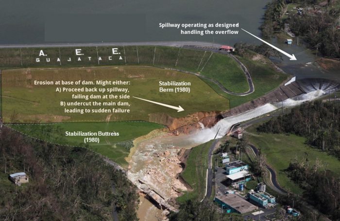
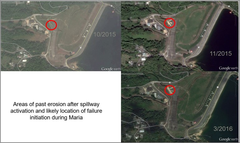
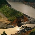
Puerto Rico had experienced severe drought conditions just a few years earlier, which reportedly led to a decision to keep the reservoir level near the spillway crest following Irma. Maria’s rainfall resulted in overtopping of the spillway weir crest by approximately 3.25 to 6.5 feet, resulting in spillway flows of up to an estimated 10,000 to 15,000 cfs. The spillway had experienced six previous flow events over its lifetime without reported incident; however, review of historic aerials shows evidence of past erosion off the side of the spillway. Ultimately, the Hurricane Maria induced flows exacerbated foundation erosion and caused failure of about 50% of the lower concrete spillway chute as well as inducing lateral erosion into the stabilization berm and buttress designed to reduce the potential for embankment and landslide acceleration.
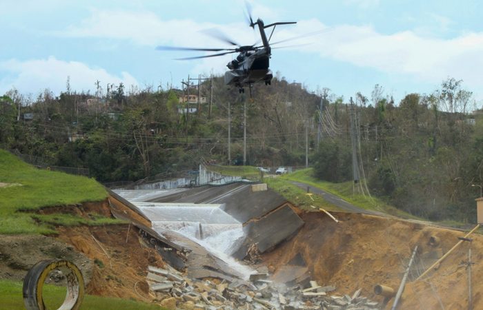
Navy helicopter about to drop Jersey barrier at the toe of what remained of the concrete chute. Toward the bottom right, note part of the 54-inch siphon line that upon damaged, cutoff water supply to the western side of the island. (Photo Source: U.S. Army Corps of Engineers, 2017)
Spillway failure is believed to have initiated with erosion of exposed landslide material at the left downstream extent of the concrete lined spillway chute and rip rap area where flows were concentrated within a slight topographic swale that directed water to the left of the 96-inch outlet works pipe headwall and back toward the river. This caused erosion of the weak landslide materials off the left side of the spillway and riprap to be shifted and transported away from the spillway toe area. Additionally, a large volume of water was simultaneously flowing through large cracks, open joints, and gaps between slabs in the spillway allowing flow under the slabs and into the weak and deteriorated underlying foundation materials. This hydraulic action and foundation erosion caused a deep head-cut to form in the landslide foundation materials that undermined and failed the lower two spillway slabs (Nos. 6 and 7) within about 48 hours of Hurricane Maria. Subsequently, slab No. 5 was left with a significant overhang that created a flat-bottomed scour hole and then eroded outward laterally into the stabilization berm, buttress, and underlying landslide materials around the right side of the scour hole. This lateral and undercutting erosion triggered a localized slump that failed slab No. 5 into the scour hole. After the loss of slab No. 5 the spillway flows diminished leaving a scour hole over 300 feet long, up to 200 feet wide and over 60 feet deep in the lower half of the spillway chute. The spillway failure and scour hole erosion also severed the 54-inch diameter water supply siphon and cut water off into the distribution canal system.
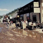
The USACE emergency assessment engineers were onsite September 24, 2017, just a few days after the landfall of the hurricane while water was still flowing over the spillway to assess the condition of the dam and develop an emergency response to prevent progressive erosion of the entire spillway, stabilize the embankment, protect the integrity of the dam, and identify potential alternatives for Interim Risk Reduction Measures (IRRM). Given the difficult access to the dam (i.e., narrow winding roads clogged with fallen debris and landslides that limited heavy vehicle access); its remoteness; the 1,200 miles separating the island from the US mainland and related supply chain issues; and the lack of power and fuel to transport and place erosion control materials such as riprap, armor stone, or concrete, the team determined the only locally available and transportable materials consisted of concrete Jersey barriers identified in storage yards within the northwest portion of the island. US Navy and Marine helicopters dropped over 500 of these barriers at the edge of the failed portion of the spillway within the scour hole to protect it against further erosion. A short distance downstream and within the scour area, an 8 foot tall line of approximately 1,340 gravel-filled sacks were placed by US Army helicopters to create a temporary stilling basin to raise tailwater in the scour hole and further decrease erosive flow velocities if the reservoir rose again over the spillway crest. In addition, ten 18-inch diameter pumps with generators connected to HDPE bypass pipelines were procured from the US mainland to re-establish the water supply to the canal and to maintain the reservoir elevation below the spillway along with clearing debris from the low-level outlet structure, which discharged downstream of the scour hole.
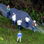
Following initial stabilization of the spillway, USACE was tasked with evaluating and developing IRRM alternatives to bring the spillway back into service (i.e., pass a similar scale Hurricane Maria hydrologic event without failure). This effort included hydrological, hydraulic, structural, and geotechnical engineering assessments to support multiple phases of risk assessments that would help inform the relative value of the selected IRRM. These studies included field investigations (i.e., geotechnical drilling, sampling, and testing; evaluation of existing site geotechnical and instrumentation data; and detailed engineering geologic mapping) that were all compiled to define the failure mechanics, geometry, and characteristics of the landslide complex.
Ultimately the studies revealed that the Guajataca River has incised into and exposed a geologic contact between a layered sequence of Miocene aged sedimentary carbonate limestone and underlying weak calcareous mudstone bedrock that are shallowly dipping to the north (in a downstream direction at the dam) approximately 4 to 8 degrees and orientated sub-parallel to the dam axis. Where the river has eroded and exposed this contact along the 2-mile-long landslide complex, it re-activates portions (nested slides) episodically and discontinuously as the slide mass is continually re-adjusting to the destabilizing toe erosion facilitated by precipitation and potentially seismic activity resulting in backfilling of the strain with further up-slope adjustments and deformation. At the dam and spillway, the basal (i.e., deepest) landslide shear plane was found to be 30 to 50 feet below the spillway surface; the construction of the dam and reservoir likely caused re-activation and re-adjustment of the failure direction due to the increased static and pore pressure loading; and the basal shear plane appears to have been partially removed around the base and perimeter of the scour hole but still remains under the upper spillway and under the embankment on the left side of the river alignment.
The emergency stabilization and re-establishing water supply measures discussed above were implemented under the phase of the project designated as Stage 1. The risk-informed selection of the IRRMs were implemented under Stage 2, which consisted of two volumes of spillway modifications:
Stage 2, Volume 1:
- Flow-able fill placed below the undermined and failed slab and encompassing collapsed portions of spillway slab, Jersey barriers, and additional riprap stone placed under the Vol. 1 efforts.
- Sealing and repairing existing large cracks in slab and performing filling of voids below the slab
- Install 23-foot deep soil anchors into the landslide materials to secure the existing slab
- Construct buttress wall to protect exposed foundation under slab No. 4 (including drains, flowable fill, anchors)
- Grout under the existing spillway slab to fill voids
- Form grouted rockfill keys within the scour area
- Re-establish water supply siphon encased in reinforced concrete
Stage 2, Volume 2:
- Place rockfill and riprap to restore original grade of spillway and buttress
- Grout the riprap cap in lifts for upper 6.5 feet.
- Install backward erosion cutoffs at critical locations
- Build a grouted rockfill stilling basin and end sill to direct flows toward river channel
- Place an 18-inch-thick reinforced concrete overlay slab over the existing slab with connections to existing drain outlets
Based on data collected from recently installed inclinometers in the vicinity of the reconstructed spillway, the foundation deformations and landslide creep at both the spillway and the embankment should be expected to continue over time and ultimately cause structural damage to the IRRM spillway repair and potentially reduce its reliability to pass the design flood event. In addition to the potential hydrologic, static, and seismic loading deficiencies of the spillway, the outlet works and embankment structures likely warrant a full risk assessment and Dam Safety Modification Study (DSMS) to evaluate and develop engineering alternatives to improve the long-term integrity and safety of the entire dam and spillway structure.
References
(1) Loar, T.N., Zeveney, D.J., and Bermudez, J. (2021). Failure, Emergency Response, Mitigation and Engineering Geology of Guajataca Dam Spillway, Puerto Rico. 2021 USSD Annual Conference Proceedings. United States Society on Dams.
(3) Kendall, J.R. and Batchelder-Adams, Gregg, P. (2021). Guajataca Dam Spillway Failure Emergency Response and Spillway Failure Assessment. USSD 2021 Annual Conference Proceedings. United States Society on Dams.
(4) Gillan, C. (2021) Guajataca Dam Spillway Failure Overview. USSD 2021 Annual Conference Proceedings. United States Society on Dams.
(5) Zeveney, D.J. (2018). Guajataca Dam. USACE Geotechnical, Geologic, and Materials Community of Practice 2018 National Convention. U.S. Army Corps of Engineers.
(6) Hutsell et. al. (2021). Interim Risk Reduction Measures (IRRM) for Guajataca Dam, Puerto Rico after Hurricane Maria (2017). USSD 2021 Annual Conference Proceedings. United States Society on Dams.
Acknowledgements: Jose Bermudez, Edgardo Bermudez, PREPA; Dan Blaydes, Dennis Zeveney, Chad Gillan, Carla Roig-Silva, Rafael Morales, and Rafael Rios (SAJ project development team); John Kendall and Chris Papiernik (SAJ risk assessment team); and Gregg Batchelder-Adams, Chuck Redlinger, Thomas Terry, Mike Phillips and Sal Todaro at the RMC.
This case study summary was peer-reviewed by Dennis Zeveney, USACE; Jose Bermudez, Puerto Rico Electric Power Authority; Gregg Batchelder Adams; USACE; John Kendall, USACE; Thomas Terry, USACE; and Sam Hutsell, USACE.
Summary
Photos
-

- Project location map. (Photo Source: Google Earth)

-

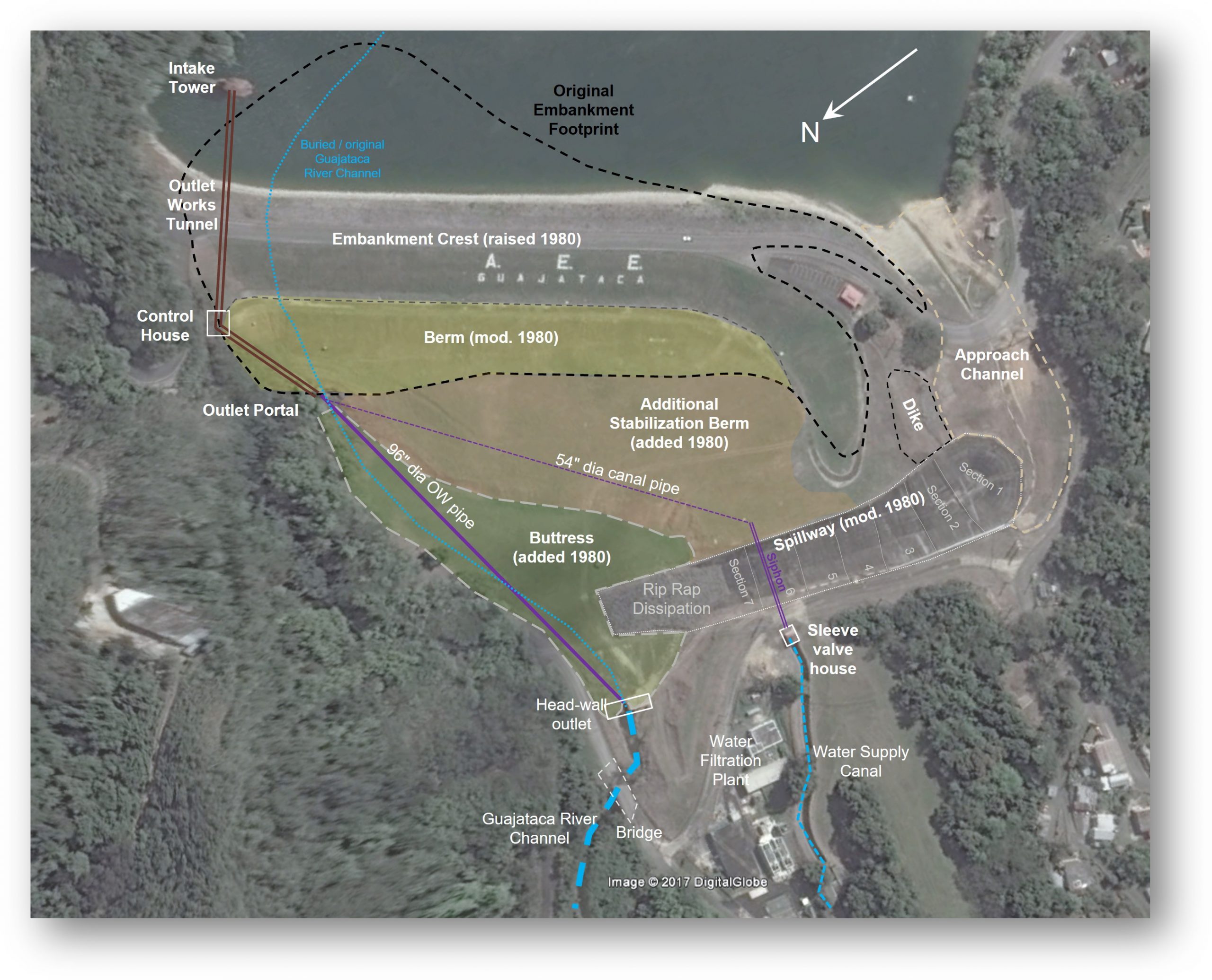
- The Guajataca Dam layout with the major features annotated. (Photo Source: Google Earth)
-
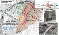
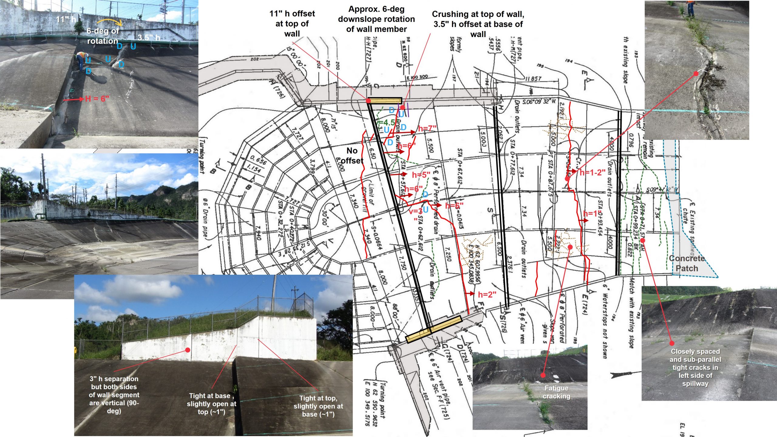
- Pre-construction topographic plan and dam layout with typical section and original construction photos. Reported site distress and deformations annotated for reference. (Photo Source: PREPA project files)
-
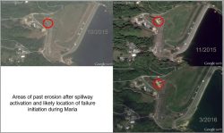
- Erosion off left side of spillway following previous spillway activation. (Photo Source: Google Earth)
-
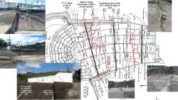
- Spillway distress (i.e., cracking, offsets, deformation mechanics) mapping and photos. (Photo Sourece: PREPA project files & U.S. Army Corps of Engineers)
-

- PREPA project files & USACE aerial photo of damaged spillway. (Photo Source: U.S. Army Corps of Engineers, 2017)

-

- Navy helicopter about to drop Jersey barrier at the toe of what remained of the concrete chute. Toward the bottom right, note part of the 54-inch siphon line that upon damaged, cutoff water supply to the western side of the island. (Photo Source: U.S. Army Corps of Engineers, 2017)

-
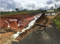
- Guajataca spillway close-up around 24 September 2017. The severed 54-inch water supply pipe is in lower left, small, localized slump that failed slab #5 is annotated.(Photo Source: U.S. Army Corps of Engineers, 2017)

-
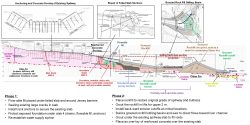
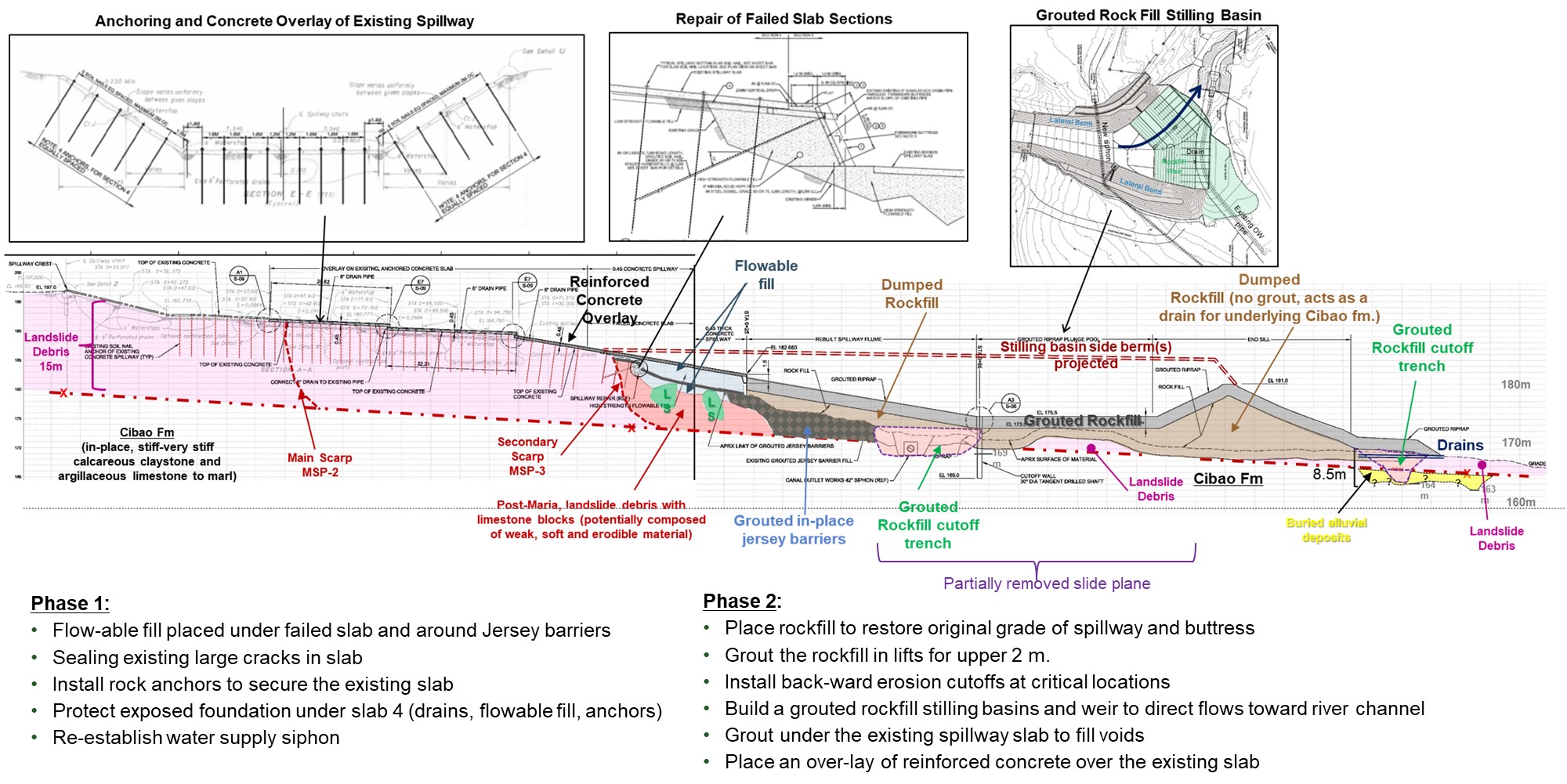
- Engineering geologic cross section with IRRM construction measures. (Photo Source: U.S. Army Corps of Engineers)
-
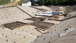
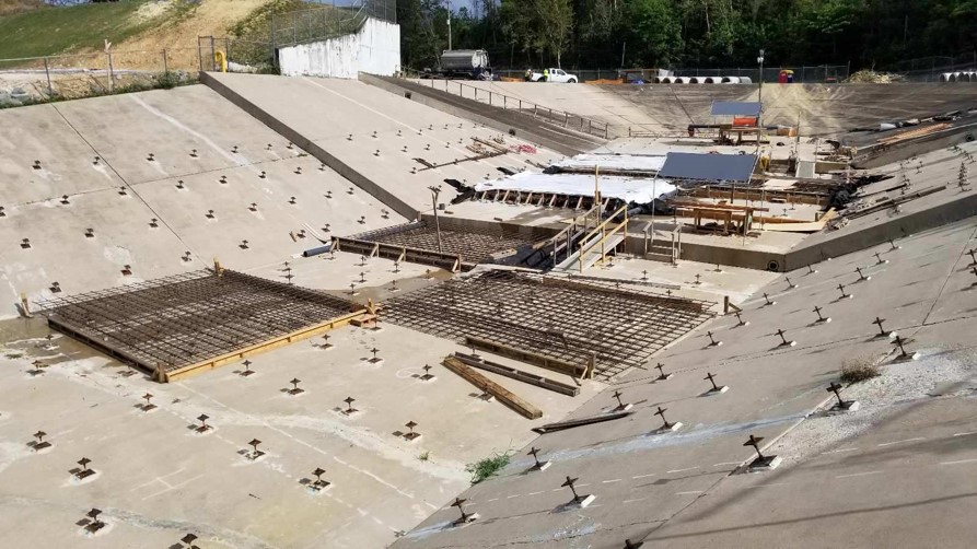
- Looking upstream from the left side of the spillway. Note anchors and concrete overlay slabs at different stages, some recently poured and protected, some with forms ready for concrete pouring and at least one with just reinforcement bars. (Photo Source: U.S. Army Corps of Engineers & Del Valle Group)
-
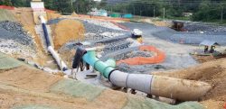
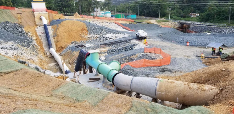
- Looking downstream from right side of the spillway, ca. Jan 2019. Note existing concrete pipe on the right, transitioning to the 54-inch siphon under the spillway. Also note most of the site was by then, backfilled. (Photo Source: U.S. Army Corps of Engineers & Del Valle Group)
-
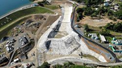
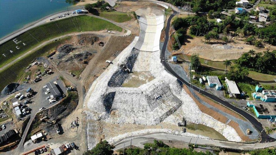
- Aerial of reconstructed spillway (IRRM). Note concrete section upstream, and grouted riprap section downstream, with plunge pool (stilling basin) area. (Photo Source: U.S. Army Corps of Engineers & Del Valle Group)
-

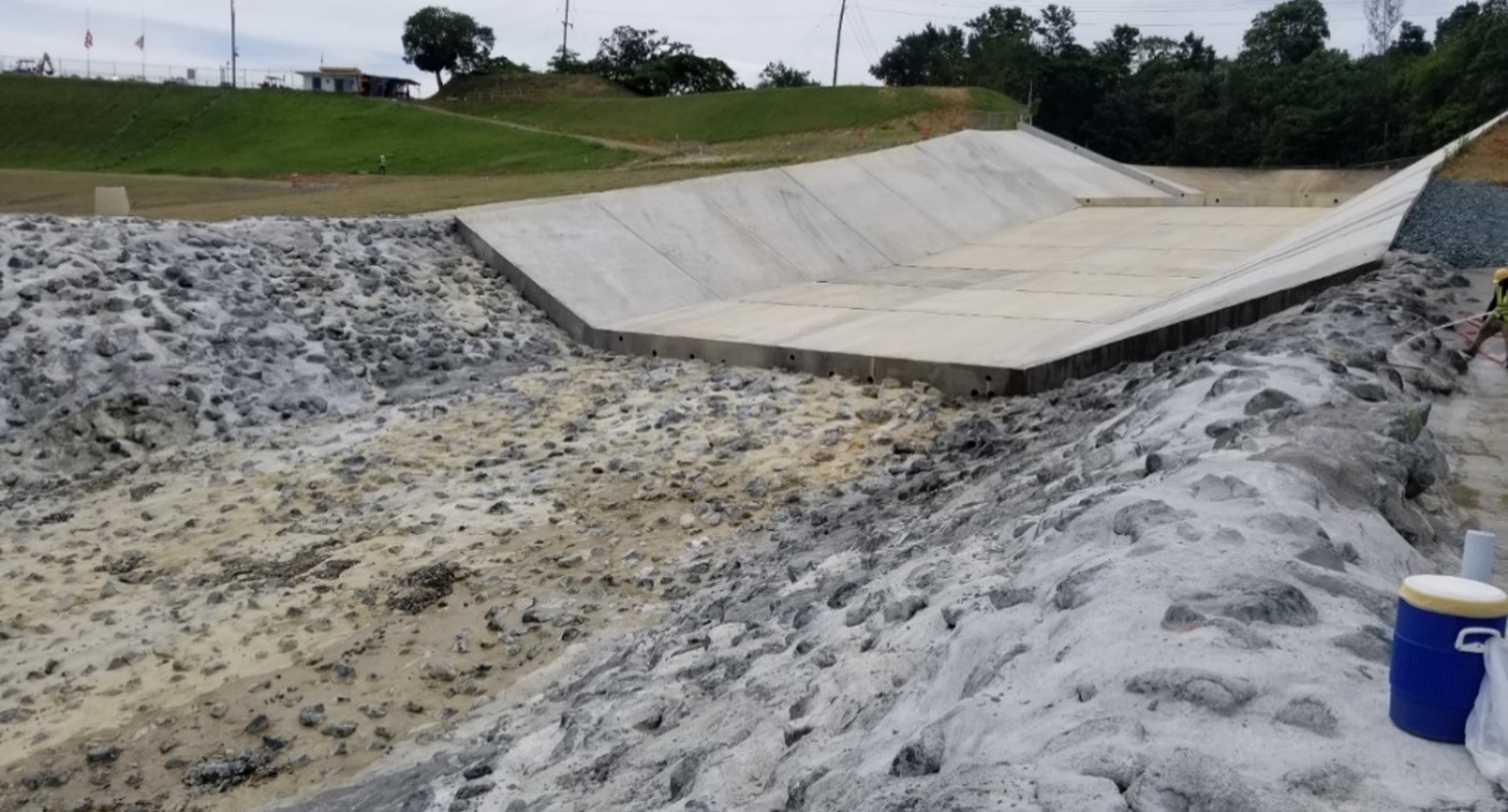
- Looking upstream from the left side of the spillway toward the transition zone, between reinforced concrete overlay section and grouted riprap section of the spillway chute. (Photo Source: U.S, Army Corps of Engineers & Del Valle Group)
-
- Spillway upon completion of Interim Risk Reduction Measures. (Photo Source: U.S, Army Corps of Engineers & Del Valle Group via Kendall and Batchelder-Adams, 2020)
Videos
-

- Guajataca Dam update on repairs, December 10, 2017
-

- Guajataca Lake Nears Dam Failure, September 22, 2017 – News report
-

- Hurricane Maria: Failing Dam Puts Many Residents In Puerto Rico At Risk | NBC Nightly News, September 24, 2017
-

- U.S. Marines Repair Hurricane Damage to Guajataca Dam, Puerto Rico, December 11, 2017
-
- Guajataca Lake Spillway Update, September 24, 2017
-

- Guajataca Dam Failing In Puerto Rico, Forcing ‘Extremely Dangerous’ Situation, September 22, 2017
-
- Guajataca Dam overflight, Puerto Rico, April 24, 2018
Lessons Learned
Concrete-lined spillways are vulnerable to significant damage and potential reservoir breach if flows are not safely contained within the conveyance structure.
Dams should be thoroughly assessed for risk using a periodic risk review process including a site inspection, review of original design/construction/performance, and analysis of potential failure modes and consequences of failure. The completed review supports a case for taking risk-informed actions at individual dams and for prioritizing actions for an inventory of dams.
Downstream of constructed spillway exit channels, spillway outflows can erode and even breach dam embankments and can adversely impact the operation of outlet works.
Intervention can stop or minimize consequences of a dam failure. Warning signs should not be ignored.
Additional Lessons Learned (Not Yet Developed)
1. Long-term landslide deformations within the foundation of dam and spillway features are likely to cause continued structural damage that can increase and change the risk of a failure over time.
2. Past spillway flow performance does not necessarily provide indication of future performance due to temporal effects and potential changes (foundation deterioration, shifting, cracking, plugging of drains, degradation of anchor systems, etc.)
3. Maintain reservoir operating water levels recommended by the designer and/or dam safety engineers (do not alter operations manual nor deviate from it without consulting with designer)
4. Ensure dam is in proper operational/working order, with particular emphasis on periodically inspecting, maintaining, and operating outlet works gates to provide a high level of reliability to lower the reservoir during an emergency and that the spillway is maintained.
5. Provide scour protection to natural ground downstream of spillway chutes, especially in the transition zone and where high, erodible flow velocities are expected and/or where there is evidence of poor past performance of the erosion protection measures.
6. Perform adequate geotechnical investigations during design and construction to maximize knowledge of site geology. Consult/hire a team of geologic/geotechnical subject matter experts.
7. Monitor and evaluate instrumentation data periodically, perform surveys (e.g., lidar, geophysics, deformation) and update/repair/replace when it becomes faulty or unreliable.
8. Address issues with dam structure as soon as they come to light. Spillway had cracks that had been sealed from time to time, but not as soon as they would open/form and rip-rap has been previously shifted and foundation material exposed during previous high flow events.
9. Perform routine dam safety evaluations (e.g., inspections, PFMA, and/or risk assessments on regular basis). Risk assessments likely would have highlighted the potential for failure of the spillway with evidence of past erosion in this area.
10. Periodically update the Emergency Action Plan, including performing tabletop exercises and updating inundation maps to identify potential downstream inundation areas with warning procedures for different failure modes.
11. Prepare inundation maps for both dam breach and non-breach conditions at different flood pools. Engage local law enforcement and emergency responders in tabletop exercises.
Other Resources

Federal Guidelines for Dam Safety Risk Management
Author: Federal Emergency Management Agency

Guidelines for Use of Pumps and Siphons for Emergency Reservoir Drawdown
Author: Morrison Maierle, Inc.
Guidelines published by Morrison Maierle, Inc.

Landslides: Investigation and Mitigation
Author: Transportation Research Board, National Research Council (Turner and Schuster)
Special Report 247

Evaluation and Repair of Concrete Structures, EM 1110-2-2002
Author: U.S. Army Corps of Engineers
Engineering Manual for USACE
Recommended Guidelines for Safety Inspection of Dams, ER 1110-2-106
Author: U.S. Army Corps of Engineers
Engineering Report for USACE
Flood Emergency Plans: Guidelines for Corps Dams
Author: U.S. Army Corps of Engineers
Guidelines for USACE
Hydraulic Design of Spillways, EM 1110-2-1603
Author: U.S. Army Corps of Engineers
Engineering Manual for USACE
Uplift and Crack Flow Resulting from High Velocity Discharges Over Open Offset Joints
Author: U.S. Bureau of Reclamation
Laboratory Studies, Report DSO-07-07
Landslide Risks
Author: U.S. Bureau of Reclamation & U.S. Army Corps of Engineers
Best Practices and Risk Methodology, Chapter VIII-2