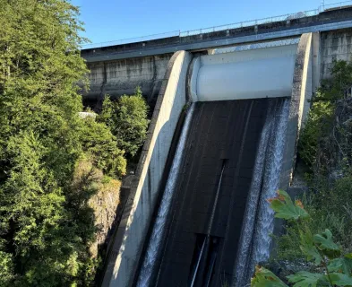
Spillway structures pass flood flows from the reservoir elevation down to the stream channel invert elevation. This generally results in high velocity flow within the spillway conveyance feature with large unit discharges during a flood event. If the spillway structure is constructed in competent rock that is resistant to erosion or if the spillway structure will be used very infrequently (and the expected erosion damage is acceptable), the conveyance portion of the structure can be constructed in natural materials, with no additional protection provided. However, in most cases, a concrete-lined conveyance feature is provided to protect the spillway foundation. Conveyance structures are typically used to convey spillway flows from a crest structure at the upstream end to an energy dissipation structure at the downstream end. Conveyance structures generally consist of concrete chutes or concrete lined tunnels or conduits.
The integrity of the concrete lining for a conveyance structure is critical to ensure the safe movement of spillway flows. If the concrete lining is compromised during a flood event, the foundation will be subjected to high velocity flows. Depending on the erosion resistance of the foundation, this could lead to scour, progressive removal of additional portions of the concrete lining, and headcutting. If the headcut progresses, the crest structure could ultimately be undermined and removed, resulting in a breach of the spillway and an uncontrolled release of the reservoir. The concrete lining of the conveyance structure can be compromised in a number of ways, including:
- Flotation of a chute slab due to uplift from seepage through the foundation or from flows infiltrating the lining.
- Stagnation pressures leading to slab jacking or erosion of foundation materials supporting the slab.
- Cavitation or ball milling damage, which can progressively remove the concrete lining.
- Overtopping of chute walls, which can remove backfill material and undermine the floor slab.
Each of these mechanisms is described in more detail below.

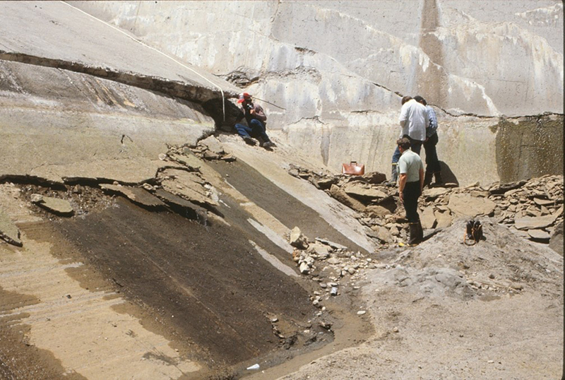
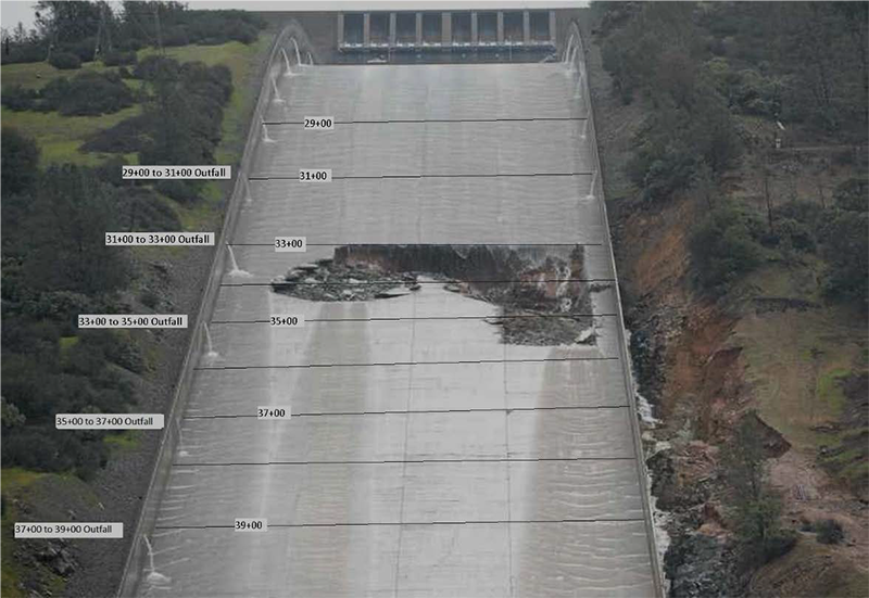
Floatation of Chute Slab: Concrete linings can fail due to flotation, where uplift pressures exceed the resistance capacity of the chute. This can occur with no infiltration of flow through the concrete lining but simply from uplift pressure generated by foundation seepage beneath the conveyance structure. Drains are effective in preventing the build-up of uplift pressures, but if drains have not been provided or if the existing drains are compromised, uplift pressures can initiate this mechanism. Uplift can be enhanced by flows which infiltrate through open cracks and joints in the concrete lining. Significant flows can infiltrate the concrete lining, even without offsets into the flow which can generate high stagnation pressures. A case history where uplift was the initiating event for failure of the concrete chute slab is the Oroville Dam Flood Control Outlet (FCO; service spillway) chute failure in 2017 (Independent Forensic Team, 2018).
Stagnation Pressures: Concrete linings can fail due to stagnation pressures which are generated at offsets into the flow at open transverse joints or cracks in a concrete chute slab. Figure 1 depicts this mechanism. Stagnation pressures can result in two outcomes which are detrimental to the stability of a concrete chute slab. The stagnation pressures can result in very high uplift pressures due to the conversion of a portion of the velocity head to a static head which can lead to slab jacking and removal of a section of the concrete lining. Figure 2 can be used to estimate stagnation pressures generated by offsets into the flow (from Wahl et al. 2019). Failure of the chute slab can result if the uplift generated by stagnation pressures exceeds the resisting forces provided by: the weight of the concrete slab and the water in the chute; anchor bars which attach the chute to the foundation; and reinforcing steel which can allow for load transfer to sections of the chute slab not subjected to stagnation pressures. Case histories where chute slabs failed due to stagnation pressures and slab jacking include the Big Sandy Dam Spillway and the Dickenson Dam Spillway (see Best Practices: Reclamation and USACE, 2019) as well as the Whaley Bridge Dam Spillway (Balmforth, 2020). The second outcome which can be adverse to the stability of concrete chutes subjected to stagnation pressures is the erosion of foundation material and loss of support for the slab. Offsets into the flow can result in high velocity flow being injected through the slab and into the foundation. If there are unfiltered exits within the foundation (which often is the underdrain system), foundation materials can be removed creating voids and a lack of support for the chute slab. If the void becomes large enough, the slab may not be able to span the void and the slab could fail by collapsing into the void. Case histories where stagnation pressures led to foundation erosion and voids underneath the chute slab are the Hyrum Dam Spillway (see Best Practices: Reclamation and USACE, 2019) and the Whaley Bridge Dam Spillway (Balmforth, 2020).

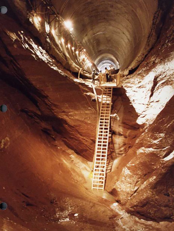
Cavitation Damage: There are other processes where the concrete lining is gradually removed over a longer period. These mechanisms include cavitation damage and ball milling of the concrete surface. Cavitation damage is initiated by spillway flows over a defect along the flow surface. The defect creates localized negative pressures within the flow which create vapor bubbles. Individual vapor bubbles converge and form larger vapor cavities. When the vapor cavities impact the flow surface they implode and generate large forces which damage the flow surface. Cavitation generally requires long flow durations (weeks or months) to produce significant damage (see Figure 3 from Falvey, 1980a). The potential for cavitation damage to initiate can be predicted with the cavitation index, which is a function of the flow velocity, the pressure along the flow surface and the vapor pressure of water. A case history of extensive damage to the spillway lining and foundation due to cavitation is the Glen Canyon Dam Spillway (see Best Practices: Reclamation and USACE 2019). Ball milling is a mechanism in which cobble and gravel sized material is introduced into a hydraulic jump stilling basin and remains in place. The trapped material is caught in a cyclical flow pattern that abrades the concrete surface. Significant concrete damage can occur, but it takes very long durations (see Best Practices: Reclamation and USACE 2019).

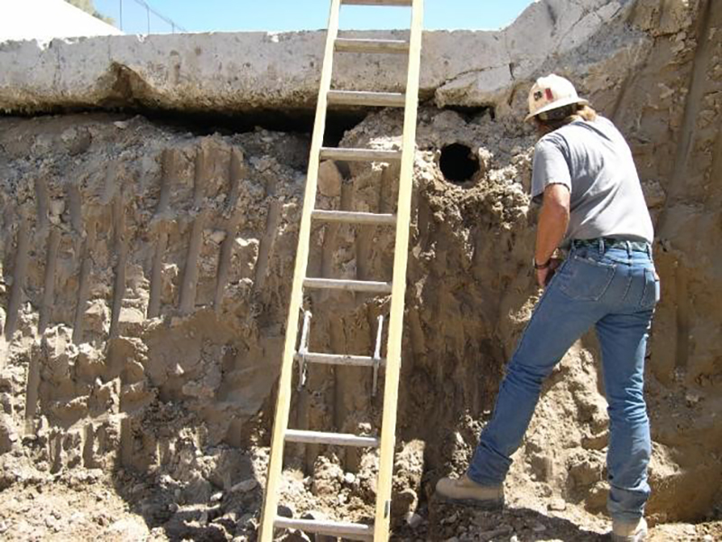
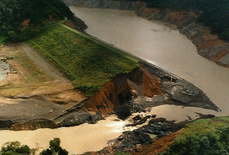
Chute Wall Overtopping: The last mechanism discussed here that can compromise the concrete lining of the conveyance structure is overtopping of the chute walls (stilling basin walls would also be a possibility, but the outside of the walls will likely be protected by tailwater and the distance that erosion and headcutting would have to travel make this pathway less likely). If chute walls overtop, the wall backfill (typically consisting of pervious material) will likely be easily eroded. Given enough duration of overtopping flows, the foundation for the chute will be exposed to erosive flows, with the potential for undermining the floor slab and ultimately failing the spillway chute. A case history in which the chute walls overtopped, and failure of the chute led to headcutting and breach of the reservoir through the crest structure area is the El Guapo Dam Spillway (see Best Practices: Reclamation and USACE, 2019). The El Guapo Dam Spillway failure was caused by a flood that exceeded the design flood for the dam.

All the mechanisms described above can lead to failure of a section of the spillway lining and expose the conveyance structure foundation. Once a section of the spillway lining has failed, the potential for erosion and headcutting through the foundation will be a function of the erodibility of the foundation materials and the energy in the spillway flows. An approach for evaluating the erosion potential is the Streampower-Erodibilty Index Method (see Best Practices: Reclamation and USACE, 2019 for details of this method). If the stream power of the spillway flows exceeds the Erodibility Index sufficiently, the foundation will likely erode and experience headcutting. Figure 4 provides empirical data that can be used to predict whether erosion will occur based on the relationship of stream power to the Erodibilty Index of the foundation. One consideration for headcutting progressing upstream is that the source of water and energy resulting in headcutting must be maintained as the structure is progressively failed in the upstream direction.
There are several defensive design measures that can be implemented to mitigate the potential for the failure mechanisms described above. Figure 5 depicts some of these measures at a transverse joint in a chute slab. Each of these defensive design measures serves a specific purpose:
- Functioning underdrains reduce uplift pressures beneath a spillway chute slab, which should mitigate the potential for flotation or stagnation pressure failure of the chute. Filtered underdrain systems prevent the migration of foundation materials into the drains and should help prevent the development of voids in the foundation from seepage beneath the slab.
- Waterstops across chute slab joints prevent the infiltration of flow through the joints.
- Joint geometry details like those shown in Figure 5 prevent the movement of the downstream slab at a transverse joint creating an offset into the flow by ensuring that the slabs on both sides of the joint move together.
- Continuous reinforcement across the joint also helps prevent relative movement across the joint and provides additional support if the chute slab is subjected to localized uplift pressures.
- An additional stability measure not shown in Figure 5 is the use of anchor bars, which attach the slab to a rock foundation. This provides additional resistance against uplift pressures.
- Mitigation measures for cavitation include providing and maintaining a concrete flow surface without irregularities or defects that could initiate cavitation damage. If the cavitation indices are low enough (generally less than 0.2), the introduction of air into the flow through a ramp or an air slot may be needed to prevent the potential for cavitation damage.
- Overtopping of chute walls can be mitigated by providing walls with adequate height. Consideration of air bulking in the flow and standing waves on the flow surface should be part of the evaluation of the wall heights (see Falvey 1980b).

All of these defensive design measures and considerations should be part of the design of a new spillway conveyance structure. The presence or lack of these key design features should be part of the evaluation of an existing spillway conveyance structure.
References:
(1) Annandale, G.W. (1995). Erodibility. Journal of Hydraulic Research, 33:4, pp. 471-494, DOI: 10.1080/00221689509498656
(2) Balmforth, D. (2020). Toddbrook Reservoir, Independent Review Report, February 10, 2020.
(5) Falvey, H.T. 1980a. Cavitation in Chutes and Spillways, Engineering Monograph No. 42. Bureau of Reclamation, Water and Power Resources Service, Denver, Colorado. April 1980.
(6) Falvey, H. T. (1980). Air-Water Flow in Hydraulic Structures, Engineering Monograph No. 41. Bureau of Reclamation, Water and Power Resources Service, Denver, Colorado.
(8) Wahl, T,L., Frizell, K.W., and Falvey, H.T. (2019). “Uplift Pressures below Spillway Chute Slabs at Unvented Open Offset Joints,” ASCE Journal of Hydraulic Engineering, 2019, 145(11): 04019039.
This lesson learned summary was peer-reviewed by Thomas Hepler, P.E., Schnabel Engineering; and Lee Mauney, P.E., HDR.


El Guapo Dam (Venezuela, 1999)

Glen Canyon Dam (Arizona, 1983)

Guajataca Dam (Puerto Rico, 2017)

Oroville Dam (California, 2017)

Palagnedra Dam (Switzerland, 1978)

Toddbrook Reservoir Dam (England, 2019)
Additional Case Studies (Not Yet Developed)
- Big Sandy Dam (Wyoming, 1983)
- Hyrum Dam (Utah, 2003)
- Dickenson Dam Spillway (North Dakota, 1954)


Block Theory Application to Scour Assessment of Unlined Rock Spillways

Design Standards No. 13: Embankment Dams - Chapter 5

")
Hydraulic Design of Flood Control Channels


Spillway Chute Joints - The Devil's in the Details

Structural Design of Concrete Lined Flood Control Channels
Additional Resources Not Available for Download
- Annadale, G. (2003). Scour Technology. McGraw-Hill, New York.