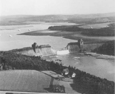
At approximately 5 a.m. on March 14, 2006, following a four-week period of heavy rainfall, Ka Loko Dam experienced an unexpected, catastrophic, and massive breach that quickly drained nearly the entire reservoir. Ka Loko (historically also “Koloko” or “Kaloko”) Dam was a century-old hydraulic fill dam located on the northeastern flank of the island of Kauai, Hawaii. The sudden release of an estimated 325,000,000 gallons (1,000 acre-feet or 1,230,000 m3) of water created a tremendous flood wave that raced down the narrow canyon of Wailapa Stream, toppling stands of trees, stripping stream sediments down to bedrock, overtopping but not failing another dam, and shooting over the Kuhio Highway embankment en route to the Pacific Ocean. Seven unsuspecting victims residing in the narrow valley downstream of Kuhio Highway, one of which was a pregnant woman, perished in the floodwaters.
Embankment
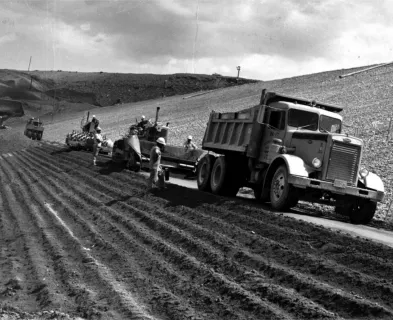
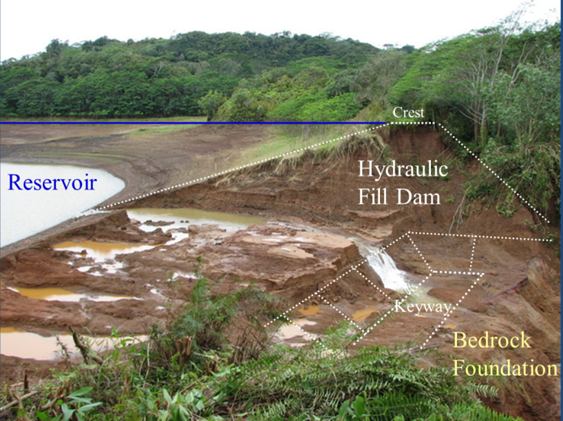
The reservoir was created by constructing a hydraulic fill dam across the small Wailapa Stream for the purpose of storing water for irrigation of the Kilauea Sugar Plantation, which operated for nearly a century between 1877 and 1971. State records indicate that the dam was originally constructed circa 1890 and subsequently raised further circa 1911-1912. The dam was constructed primarily using hydraulic fill from mining and sluicing materials from a volcanic cone at the left abutment. The sluiced fill was placed directly on top of native alluvium and late-stage volcanic bedrock. The later dam raise was made using compacted fill.
The final length of the dam was approximately 770 feet (235 m) with an embankment height of approximately 40 feet (12 m). The downstream and upstream dam slopes were generally 2:1 and 3:1 (horizontal:vertical), respectively, with localized steeper sections, particularly near the crest. The width of the crest was approximately 15 feet (4.5 m).
Hydrology and Hydraulics
The embankment created a reservoir with an estimated capacity of 1,275 acre-feet (approximately 415,000,000 gallons). The natural watershed for the reservoir was defined by a bowl-shaped feature, likely a remnant volcanic cone, which had a relatively small drainage area of 60 acres (24 hectare) – only 36% larger than the 44-acre (18 hectare) surface area of the full reservoir.

In order to fill the reservoir and maintain a desired full pool for irrigating sugar cane, surface water was supplied to the reservoir through two constructed and maintained ditches that collected and directed surface water runoff from neighboring watersheds within the adjacent Moloaa Forest Reserve. The total area of these outside watersheds was 1,110 acres (450 hectare), approximately 19 times the area of the watershed circumscribing the reservoir. Shutting off flow from both ditches meant that only rainfall in the very small watershed would be retained by the dam, less outflows and seepage. Plantation records document the substantial effort required to continuously maintain, monitor, and regulate flow in the ditches in order to maintain a full, productive reservoir without overtopping the dam.
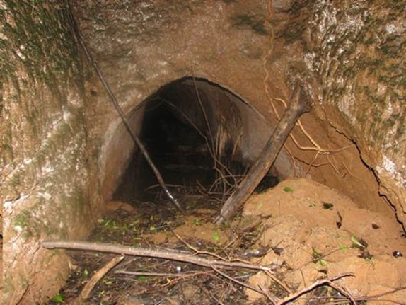
The “principal spillway,” more commonly referred to as the permanent outlet works, was meant to deliver water for irrigation. The outlet works was a 5½-feet-high (1.7 m), arched, hand-dug tunnel that penetrated the right abutment and directed water into a flume system. The flow through the tunnel was controlled using a stop log system on the reservoir side of the right abutment. This spillway allowed for robust control and rapid drainage of the reservoir.
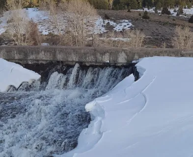
The dam also incorporated a small, unlined “overflow” channel on the right abutment near the edge of the dam. The trapezoidal earthen channel was documented by the USDA in 1982 as being 4.4 feet (1.3 m) deep and 18 feet (5.5 m) wide at the invert. Near the crest, the channel was concrete lined. The overflow channel reportedly operated at least 20 times between 1940 and 1953 with no evidence of distress to the dam or spillway. Because of long-term settlement of the embankment (up to 3 feet [1 m] of sagging at the center), the invert elevation of this overflow channel was only 1.5 feet (0.45 m) below the lowest elevation of the crest in 1982. At that time, the channel was notably overgrown and poorly maintained.
Ownership and Operation
Land ownership and the responsibility for operation of the reservoir changed following the cessation of plantation operations in 1971. The operation and maintenance became the responsibility of the Kilauea Irrigation Company, a public utility owned by C. Brewer & Co. Under this new control, the permanent outlet system was modified by plugging the 5-½-feet-high (1.7 m) tunnel and replacing it with a discharge line consisting of a single 18-inch-diameter (457 mm) PVC pipe lying at the base of the tunnel and controlled by a single valve at the downstream toe. When C. Brewer was liquidated in December 2005, Kilauea Irrigation Company was sold to HitchCo, a firm owned by Tom Hitch, who thus became responsible for maintenance and operation of the inflow ditches and outflow pipe. In 1987, legal ownership of the two parcels of land that included the dam and reservoir was transferred separately to Pflueger Properties and the Mary Lucas Estate Trust.
Hawaii Dam Safety Program
Ka Loko was initially classified as a low hazard dam by the U.S. Army Corps of Engineers. When the State of Hawaii adopted “The Hawaii Dam Safety Act” in 1987, the Corps’ designation was adopted by the State as defined as no expected loss of life and minimal economic loss due to failure. Thus, there was no emergency action plan or flood inundation map necessary for the dam. The hazard designation had not been updated by the State prior to the failure.
Antecedent Precipitation
The rainfall totals between March 2005 and January 2006 were mostly below average. The 30-day period ending on December 31, 2005 had been the driest continuous 30-day period on record at a USGS rain gage at Ka Loko Reservoir, monitored since 1949. At the time, the reservoir was reportedly nearly empty, with intake risers for the permanent outflow pipe exposed. Heavy rains ensued, with cumulative rainfall of 30.5 inches in the 30-day period ending March 13, 2006, including 3.93 inches on March 10 and 4.54 inches on March 11, 2006. This 30-day period was the 7th wettest on record for this part of Kauai since 1949. However, negligible rain (0.12 inches) fell in the two days before the breach. The peak inflows in the open ditches flowing into the reservoir would have likely occurred on March 10 and 11, three to four days prior to the failure.
Overtopping
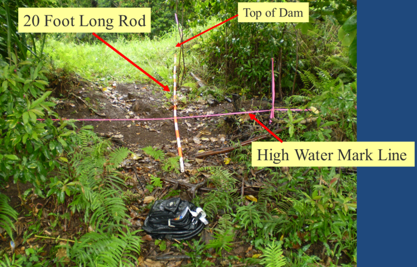
Ka Loko reservoir filled rapidly in February and March 2006 and the dam was overtopped. Measurements by the US Geologic Survey (USGS) at multiple “fair” and “good” quality debris or wash lines after the failure indicate that the average maximum height of water overflowing the dam was 6 to 7 inches (15 to 17 cm). The USGS acknowledged that multiple high water marks were identified around the reservoir but they focused only on those having the highest elevations.

Based on a hydrologic analysis of the contributing watersheds by Exponent, the overtopping likely occurred for less than one day beginning on March 10 or 11, three to four days before the failure. In fact, observations by Exponent after the failure indicated a second high water mark corresponding to the reservoir level at the time of the breach on March 14. This second high water mark was measured to be approximately 2-½ feet (0.8 m) below the lowest part of the crest of the dam.
Though the dam had clearly been overtopped, post-failure observations by multiple experts did not find evidence of surface erosion (such as ruts, rills, or gullies) on the slopes or the crest of the remnant embankment, in the remnant downstream left groin of the dam, or at the toe of the dam. There were no signs of cracking on the slope or crest.
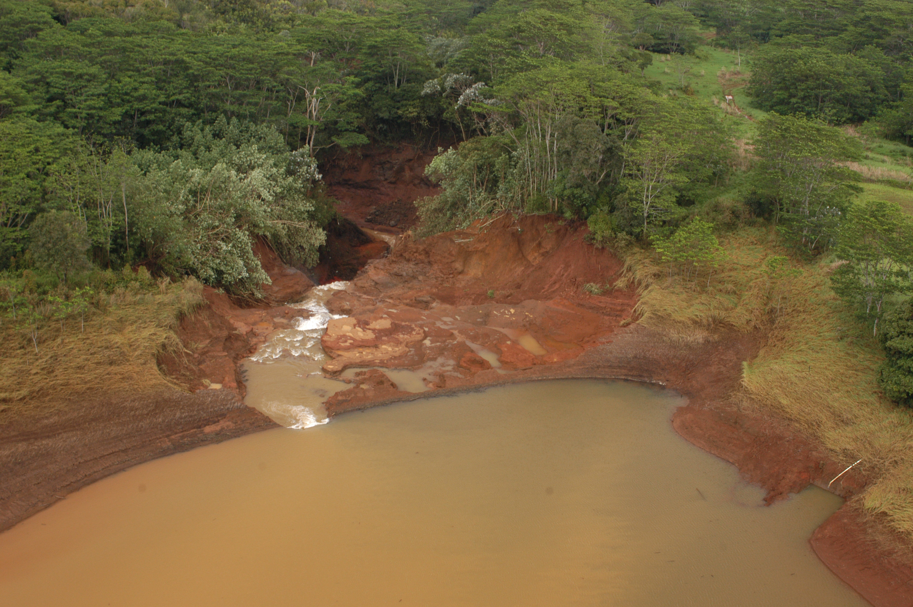
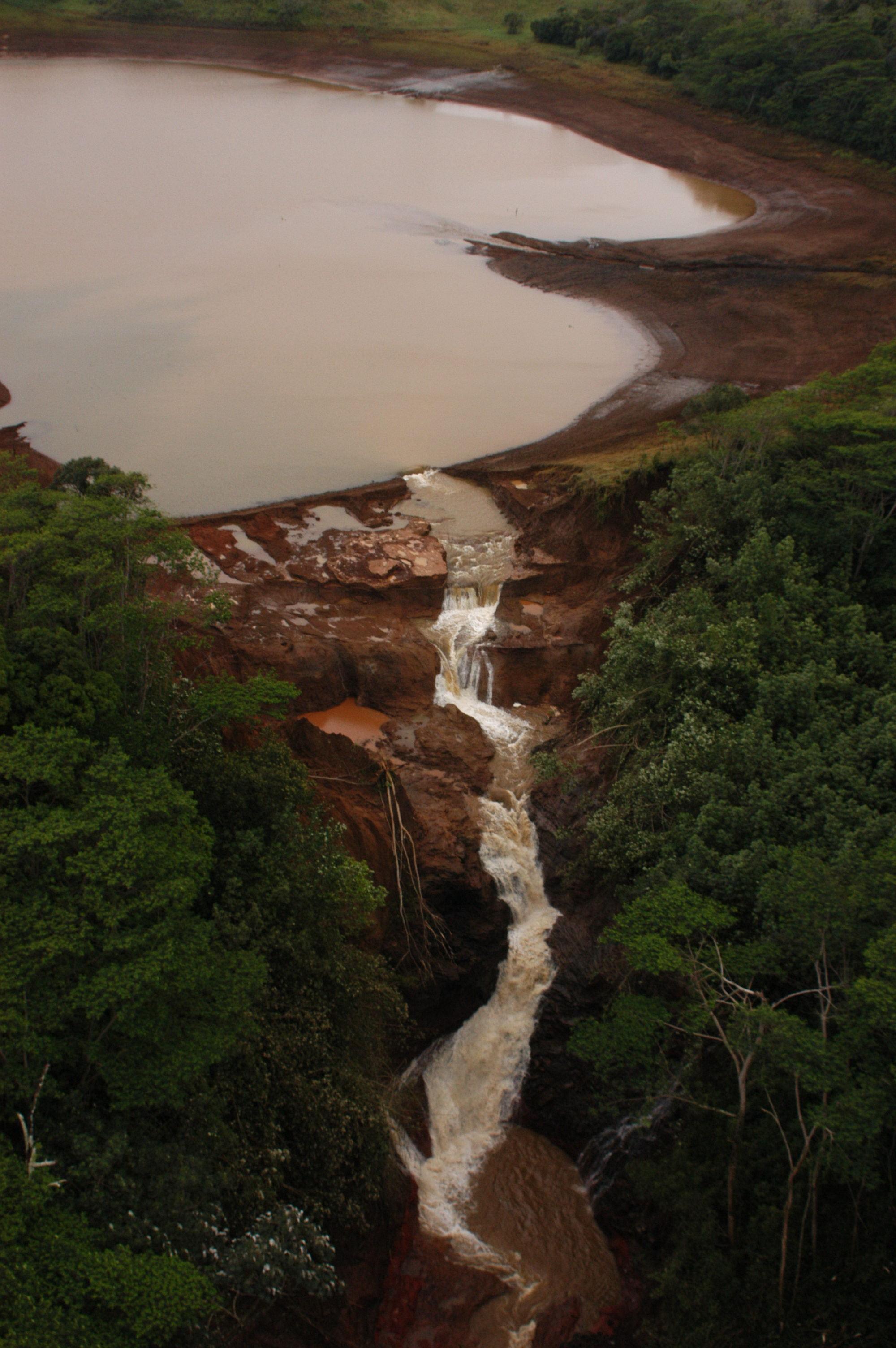
Breach
The breach in Ka Loko Dam was massive and “U”-shaped. It measured approximately 270 feet (82 m) in width at the dam crest and 165 feet (50 m) at its base. The position of the breach near the right end of the dam was generally positioned at the maximum height of the dam at the ancient stream channel. The morphology consisted of three distinct topographic benches at the base. A plunge pool located on the lowest bench indicated that a large block of material had horizontally displaced before a majority of water flowed through the breach. Based on the morphology, this breach clearly occurred very quickly.
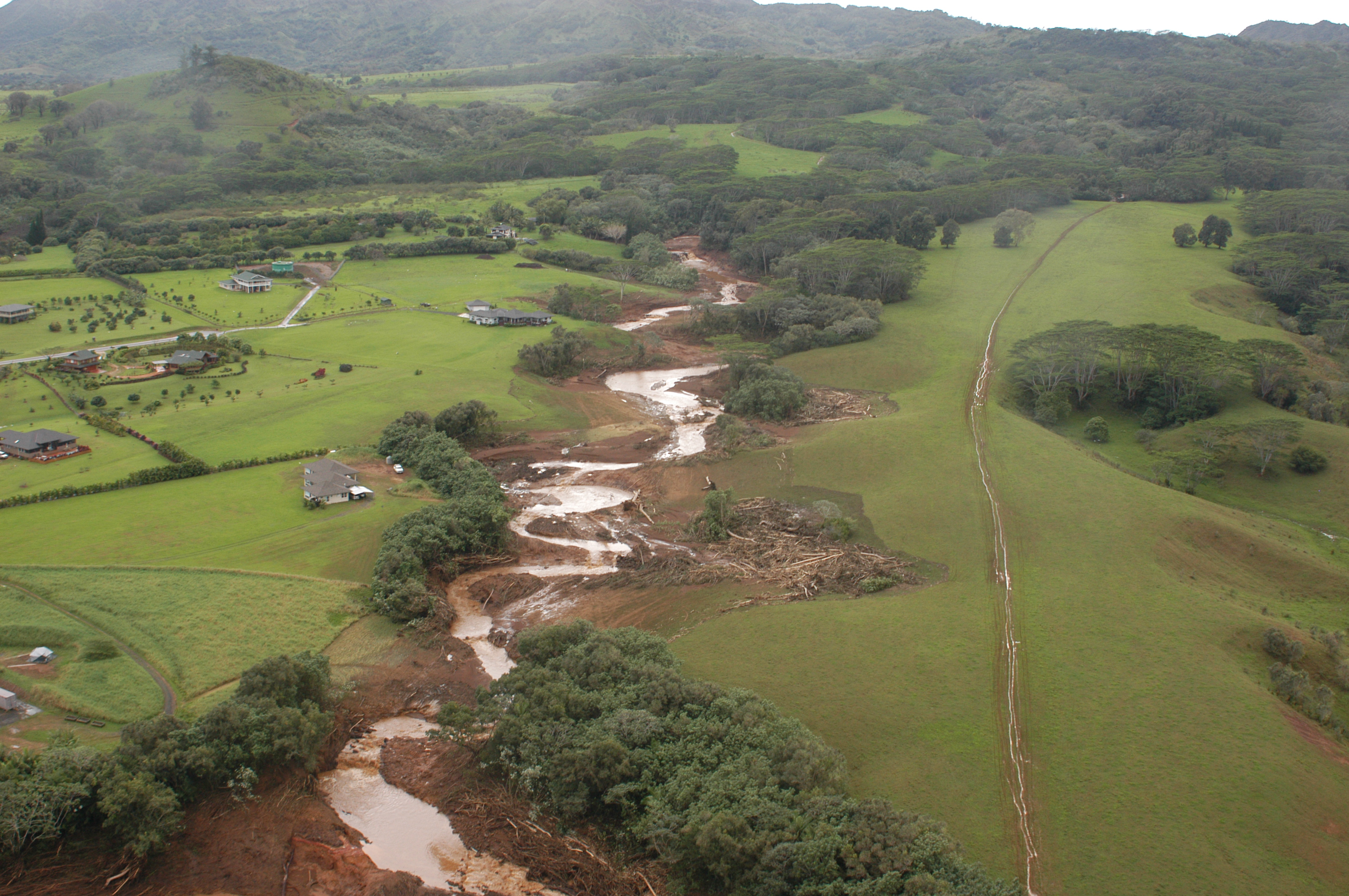
Flood Wave in Wailapa Stream
Wailapa Stream formed a winding and very narrow canyon for the first mile (1.6 km) below Ka Loko Dam. The height of the flood water in this canyon was estimated to be on the order of 30 feet (9 m) at its maximum.
Morita Dam, built circa 1920 to store water for agricultural use, was another hydraulic fill dam located approximately 2 miles (3.2 km) downstream where the canyon opened up to a broader plain. This dam was estimated to be 27 feet in height (8 m) with a crest width of 24 feet (7 m). Observations indicate that it was overtopped with approximately 20 feet (6 m) of floodwater in the initial wave and then was continuously overtopped for five days until it was purposely breached. Morita Dam did not fail as a consequence of the initial 20-foot (6 m) wave of water and being overtopped for five days. Soil samples taken and tested from Morita Dam indicate that it was constructed of earthen materials similar to those used at Ka Loko Dam.
Approximately one-half mile (0.8 km) further downstream, the flood wave engulfed the Kuhio Highway. The USGS estimated the flow in Wailapa Stream at Kuhio Highway to be 27,200 cfs (770 m3/s) with an estimated depth of flow from the channel invert of approximately 23 feet (7 m). There were eyewitnesses to the flood wave shooting over the highway.
The flood wave dissipated in the Pacific Ocean.
Failure Investigations
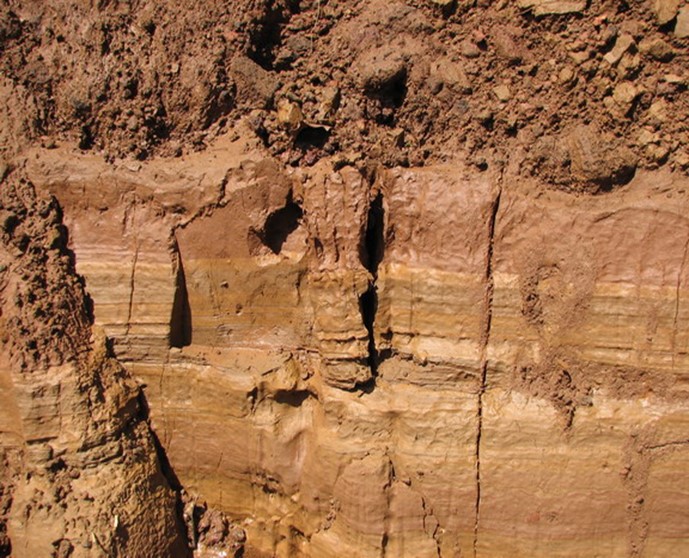
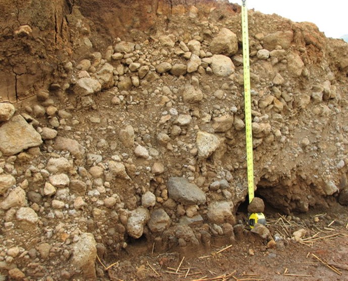
Within days of the breach, various engineering teams were called in to investigate the failure, including Exponent, Inc. (“Exponent”). The benches in the breach provided access to observe, map, and sample foundation, abutment, and embankment materials. The upper bench, originally located approximately 33 feet (10 m) below the crest of the dam, exposed gravel- and cobble-sized volcaniclastic material. The middle bench, located approximately 40 feet (12 m) below the crest of the dam, exposed alluvium over native volcaniclastic sediments. The lowest bench, originally located approximately 55 feet (17 m) below the crest of the dam, overlaid a greasy, waxy, gel-like grey saprolitic material within the late-stage volcaniclastic sediments.
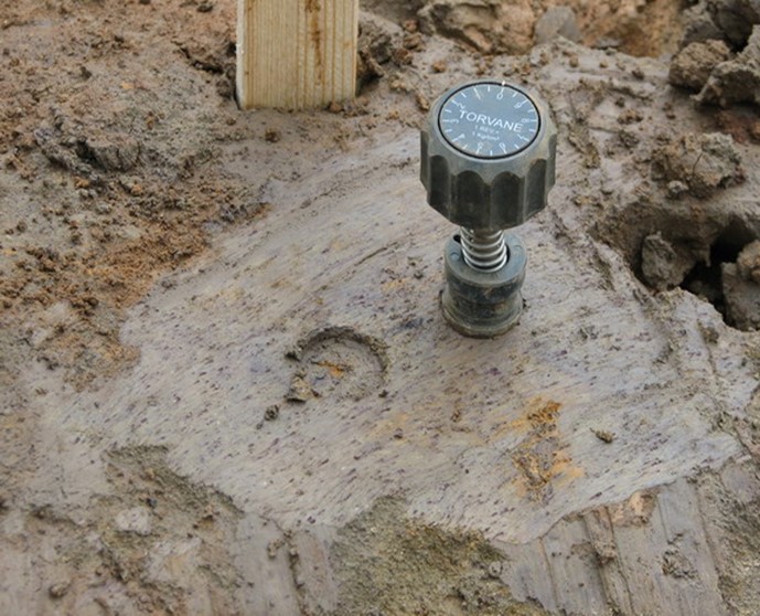
Field investigations included numerous solid-stem and hollow-stem auger borings with SPT and undisturbed sampling and in situ vane shear testing. A suite of laboratory testing was performed to identify physical and engineering properties as well as geochemical properties of the various materials.
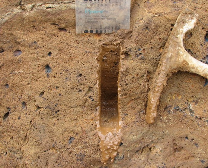
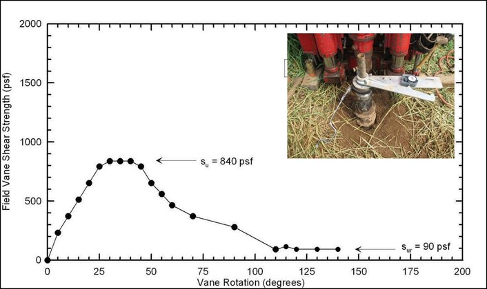
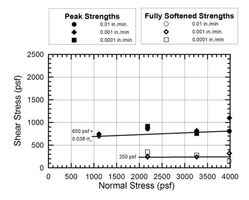
A significant focus of Exponent’s post-failure investigation was the evaluation of in-place weathering of late-stage volcanic materials that were exposed in the breach at the right abutment and foundation of the dam. Geologic mapping and geochemical testing clearly indicated a profile of increased in-place weathering of materials with depth. In situ vane shear testing of the most highly weathered material, the grey saprolite exposed in the lowest breach bench, measured a peak undrained shear strength of 840 psf (40 kPa) and a residual strength of 90 psf (4.3 kPa). Peak undrained strengths using a field torvane were in the range of 0.1 to 0.25 tsf (10 to 24 kPa). Direct shear testing of grey saprolitic material measured a peak strength internal friction of 2 degrees and cohesion of 650 psf (31 kPa). The fully softened strength had a peak strength internal friction of 0 degrees and cohesion of 250 psf (12 kPa). These results indicate that this material was weak and very sensitive to slightly quick behavior (St ~ 9). Using a scanning electron microscope (SEM), the saprolite was determined to consist largely of fine, rapidly formed, spherical halloysite clay. When subjected to drying, the halloysite converted to kaolinite, requiring special care and consideration when performing laboratory testing and microscopy.

In-place weathering of pieces of gravel in the sluiced embankment was also notable. Although this gravel was strong enough to be sluiced into place in the 1890s, exemplar pieces could be easily crushed by hand in 2006. When preparing a sample of the sluiced gravel for an LA Abrasion test, the laboratory reported that “the majority dissolved when soaked in water.” After LA Abrasion testing, there were no remaining pieces greater than 1 inch (2.5 cm).
Global stability analyses were performed using cross sections developed from pre- and post-failure geologic mapping and field investigations. Material characterizations were based on field and laboratory testing. The results of these analyses indicate that a progressive sliding failure occurred in the grey saprolite, which explains the lowest topographic bench of the failure.
Summary
Substantial evidence exists to demonstrate that the primary mode of failure was base sliding in the grey saprolite layer beneath the downstream slope of the dam. The evidence to support this mode of failure includes: 1) geologic evidence of progressive in-place weathering of volcaniclastic deposits, resulting in diminishing global stability with aging; 2) the morphology of the breach, including a plunge pool that would have formed after a block of foundation material had slid; 3) the quick formation of the breach as indicated by the initial wall of water that bore down the canyon; 4) the weak, sensitive shear strength characteristics of the grey saprolite; and 5) global stability calculations supporting this mode of failure.
Although numerous failures, primarily landslides, have been documented and associated with in-place weathering of volcanic deposits into halloysite (clay), this failure appears to be a first for the failure of a major dam. The combination of the presence of late-stage volcanic deposits in the foundation and substantial duration of dam operation created this dangerous condition. There is a much lower likelihood of in-place weathering for more competent volcanic deposits because of the difference in chemical composition.
Several experts concluded, without the benefit of hydrologic calculations or detailed geotechnical analysis, that the dam failed by overtopping. This theory was promulgated largely by the State Attorney General’s investigative study conducted by Mr. Godbey, based on a failure evaluation by his geotechnical expert. However, there is substantial evidence to suggest that overtopping was not likely the cause, or a contributing factor, to the failure. The evidence includes: 1) precipitation records indicate that only 0.12 inches of rain fell on the two preceding days (March 12 and 13); 2) hydrologic calculations by Exponent provide evidence that overtopping had ceased prior to the failure on March 14; 3) there was a second (lower) high water mark that was observed 2.5 feet (0.8 m) below the crest that likely marked the water level at the time of the failure; 4) there was no evidence of erosion in the remnant embankment, abutments, or foundation at the toe; 5) Morita Dam, built with similar materials, was overtopped with at least a 20-foot-high (6 m) flood wave and then was overtopped for 5 days with stream flow before being intentionally breached and it did not fail by overtopping; 6) the materials used to construct Ka Loko (and Morita) Dam are not considered to be highly erodible; 7) the downstream slope of Ka Loko Dam was heavily vegetated with trees and brush that would have substantially slowed the speed of water flowing over the dam; 8) the breach occurred very rapidly, as indicated by the wave of water that bore down the canyon; and 9) the morphology of the breach was less consistent with an overtopping failure.
Probably the most unique aspect of this case history and most important lesson learned is the likelihood of substantial and rapid in-place weathering of late-stage volcanic materials that occurred in the embankment and foundation of Ka Loko Dam since its construction over 100 years prior. This weathering was likely caused by continuous water seepage from a near-continuous full pool. Through this process, there would have been a rapid formation of halloysite clay at key locations in the embankment and foundation. From a stability perspective, the rapid formation of halloysite clay in the form of small, spherical particles would have created a fragile, sensitive material that could fail readily when disturbed. The halloysite-rich intervals are believed to have formed at a permeable interface in the foundation that thereafter represented a strength discontinuity. By this mechanism, the dam failure is correlated with the achievement of threshold conditions, wherein the ever decreasing shear strength and increasing lateral continuity of the halloysite-rich interval could no longer support the lateral forces applied by the dam and the impounded water. This condition was latent and would have eventually led to the failure of this dam, regardless of whether the dam was properly maintained and operated.
A contributing factor to this failure may have been the unprecedented exposure of the entire upstream slope during a period of drought in late 2005 and early 2006. Although there was no direct evidence, it is possible that desiccation cracks formed and concentrated seepage and pore pressures through the foundation of the dam, reducing global stability. The materials are not considered to be susceptible to internal erosion in the form of a concentrated leak, backward erosion, contact erosion, or suffusion.
References
(1) Godbey, R.C. (2007). Report of the Independent Civil Investigation of the March 14, 2006, Breach of Ka Loko Dam. State of Hawaii Attorney General’s Office. [includes appendix “Engineering Assessment of Breaching Failure of Ka Loko Dam,” by technical expert, Dr. Lelio Mejia]
(2) Borreca, R. & Finnegan, T. (2006). Dam bursts: Crisis on Kauai. Honolulu Star Bulletin.
(4) USGS. (2006). Peak Stage and Discharge Data for Ka Loko Reservoir Flood, Island of Kauai, Hawaii, March 2006. United States Geological Survey.
(5) USDA. (1984) Kilauea Agricultural Water Management Study Report. United States Geological Survey in cooperation with State of Hawaii Department of Land and Natural Resources.
(6) Exponent – Failure Analysis Associates (2008). Ka Loko Dam Failure, Preliminary Causation Report [Unpublished Confidential Report].
(7) Civrotech Engineering, PC. (2008). Engineering Assessment of Breaching Failure of Ka Loko Dam: Final Report.
(8) Shaller, P, Sykora, D, Doroudian, M, & Churchman, G. (2016). Rapid in situ conversion of late-stage volcanic materials to halloysite implicated in catastrophic dam failure, Hawaii. Clay Minerals, 51, 499-515.
(9) Hawaii DLNR. (2006). Dam Inspections - History [News Release]. Hawaii Department of Land and Natural Resources.
(10) Zimmerman, M. (2014). Pflueger sentenced in Kauai dam breach tragedy that killed 7 people. Hawaii Reporter.
This case study summary was peer-reviewed by Irfan Alvi, P.E. (Alvi Associates, Inc).


Lessons Learned

Dam incidents and failures can fundamentally be attributed to human factors.
Learn more
High and significant hazard dams should be designed to pass an appropriate design flood. Dams constructed prior to the availability of extreme rainfall data should be assessed to make sure they have adequate spillway capacity.
Learn more
Past successful dam performance does not guarantee future successful performance.
Learn more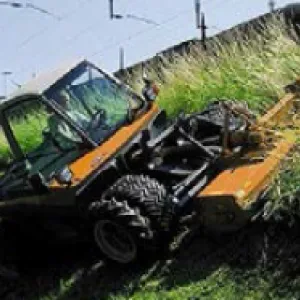
Regular operation, maintenance, and inspection of dams is important to the early detection and prevention of dam failure.
Learn more
The hazard classification of a dam can change over time (hazard creep).
Learn more
Uncontrolled vegetation on and around dams can hinder inspection and lead to serious structural damage, significant maintenance costs, and possible failure.
Learn moreAdditional Lessons Learned (Not Yet Developed)
- Many years of successful dam performance does not guarantee future successful performance.
- Dams and levees can survive overtopping; just because a dam is overtopped does not mean it failed by overtopping.
- The evaluation of the cause of dam failure may require more than a desktop study; an in-depth investigation and analysis may be required.

Design Standards No. 13: Embankment Dams - Chapter 13


Pocket Safety Guide for Dams and Impoundments

Slope Stability, EM 1110-2-1902