The Lower San Fernando Dam (LSFD) was built by the Los Angeles Bureau of Water Works and Supply (predecessor of Los Angeles Department of Water and Power (LADWP)) as part of the terminal storage system for the Los Angeles Aqueduct that included the adjacent Upper San Fernando Dam and several other dams in southern California. This was the era of engineering by William Mulholland and Henry A. Van Norman. By 1970, the Van Norman complex (Upper and Lower San Fernando Reservoirs) provided approximately 80 percent of the Los Angeles water supply.
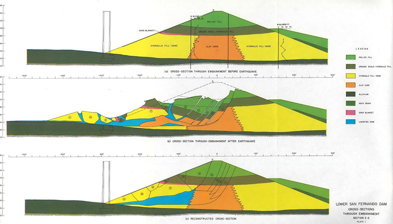
The LSFD was a hydraulic and rolled fill dam constructed beginning in 1912 at the northeast corner of the San Fernando Valley near Granada Hills. At the time of design and construction, hydraulic fill techniques were considered to produce ‘soundly engineered’ earth dams. Hydraulic fill was placed to approximate El. 1105 feet to create the dam. The shells consisted of a stratified sequence of layers of silty sand, sandy silt, and clay and the core was created from puddled clay. The relative density of hydraulic sand fill was later determined to be between 40 and 70 percent. The hydraulic fill section was capped and the dam raised with rolled earth fill in four epochs. The dam was raised for the last time in 1929-30 to a crest El. 1144.6 feet. In 1940, the last major modification to the dam was the construction of a rolled earth berm at the downstream toe up to El. 1096 feet. The maximum height of the dam was 142 feet with a length of 2,080 feet. The upstream slope was 2.5:1 and the downstream slopes were 2.5:1 (upper embankment) and 4.5:1 (berm). The crest width was 20 feet.
The embankment of the dam in the channel (deepest) section and the lower portions of the abutments was placed on recent alluvium consisting of stiff clay with lenses of sand and gravel. Reportedly, there were cutoff trenches to bedrock that were backfilled with hydraulic fill material or puddled clay. The maximum thickness of alluvium was 35 feet. Underlying the alluvium and forming the abutments are shales, siltstones, and sandstone rocks.
Two concrete outlet towers were constructed as intakes for the service flows from the reservoir. Tower No. 1 was constructed near the center of the dam and founded on rock. The outlet for this tower had a steel insert with a diameter of 62 inches. Tower No. 2 was placed near the right abutment and had an outlet with a 6-foot-diameter cast-in-place concrete pipe.

The dam was operated many years with the reservoir (Lower Van Norman Lake) near full design (spillway) El. of 1134.6 feet. However, in 1966, following technical reviews and engineering studies involving the evaluation of seismic hazards of this and many other dams in California, the maximum operating reservoir level was reduced by 9.6 feet to El. 1125 feet. The spillway invert was not changed (El. 1134.6 feet).
The 1971 San Fernando (a.k.a. Sylmar) earthquake (Mw = 6.6) occurred in the early morning hours of February 9. The earthquake was generated by thrust faulting on the Sierra Madre fault. The epicenter was located approximately 10 km northeast of LSFD at a focal depth of approximately 9 km. This earthquake caused an estimated $550M in damage, largely to buildings and a major hospital, killed 50 people, and left hundreds trapped in rubble. The instrumental intensity of ground shaking (via SHAKEMAP) at the dam is estimated to have been VII to VIII. The duration of strong ground shaking was approximately 15 seconds.
Two seismoscopes located at LSFD captured ground motions during the 1971 San Fernando earthquake. One seismoscope was located at the south (left) abutment; the other seismoscope was located on the crest of the dam near the center of the dam. Based on an analysis of these records, the peak ground acceleration in the rock foundation underlying the dam was approximately 0.6 g and researchers concluded there was no significant amplification between the foundation and the crest of the dam.
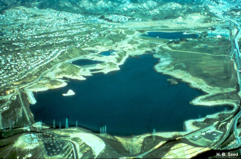
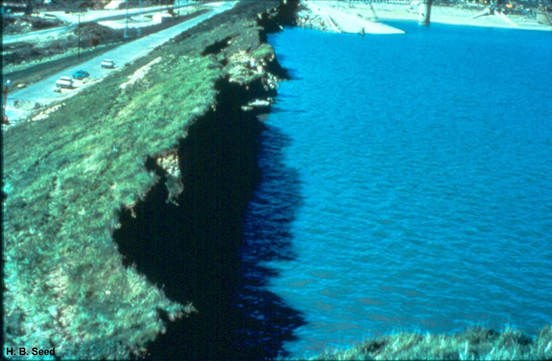
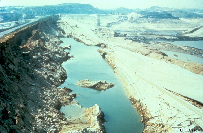
The earthquake ground shaking caused a majority of the upstream slope of LSFD, offset towards the left abutment, to fail, sliding into the reservoir and resulting in a substantial loss of freeboard. The embankment spread approximately 250 feet beyond the toe of the embankment. Further examination of the seismoscope on the crest indicated that the upstream slide developed after the earthquake had continued for some time and not during one of the peak motions.
At the time of the earthquake, the reservoir was at El. 1109 feet, which was 25 feet below the spillway, 35 feet below the crest of the dam, and 4 feet above the top of the hydraulic fill. After the failure, the resulting freeboard created by the upper edge of the slide mass was approximately 5 feet. Within minutes of ground shaking and failure, a caretaker of the dam made observations and found the reservoir to be perfectly quiet with no observable waves or sloshing.
The outlet tower near the west abutment (Tower No. 2) remained standing and was not appreciably damaged. However, the outlet tower near the center of the dam (Tower No. 1) had severed, toppled, and was not visible beneath the reservoir. The pier support system for the catwalk to this severed tower remained near vertical, however, essentially moving laterally while floating on top of the slide debris into the reservoir.
Sandbags were rushed to the site to build up freeboard. As a precaution, 80,000 residents living within a hastily defined 2 mile by 12 mile rectangular area below the dam were immediately evacuated and kept out of the area for four days while the reservoir was lowered with pumps. In the end, officials and investigators agreed that a major catastrophe was narrowly missed as 10,000 acre-feet of water in the reservoir was retained and later released in a controlled manner via pumps.

A post-failure investigation was conducted by a blue ribbon panel headed by Prof. Harry B. Seed at the University of California at Berkeley and Prof. Ken L. Lee at the University of California at Los Angeles. The focus of their investigation was liquefaction triggered by ground shaking using an approach involving a comparison of seismic shear stresses and the results of cyclic triaxial shear tests on tube samples. Another study was conducted by Dr. Castro at GEI involving the “steady-state” approach developed by Prof. Casagrande at Harvard University. This approach relied on laboratory testing of minimally disturbed samples of hydraulic fill to evaluate the in situ undrained steady state strength. This earthquake-induced liquefaction and slide continues to be the subject of analysis, discussion, and validation about the performance of hydraulic fill during earthquakes and the modeling techniques that best capture that performance (e.g., Chowdhury et al. 2019).
Profs. Seed and Lee’s study concluded that “after about 12 seconds of strong shaking very high pore water pressures had developed in an extensive zone of granular hydraulic fill near the base of the embankment and upstream of the clay core so that much of this soil was in a liquefied condition. At this stage, the shear resistance of the soil in the upstream shell could not withstand the dead load stresses caused by the weight of the embankment and slide movements developed. The slide mass moved outwards on the liquefied soil, breaking into blocks as the movement developed and removing support from the clay core, which was then extruded into the remaining part of the shell material by the pressure of the overlying portions of the embankment.”
Dr. Castro’s study concluded that the estimated in situ undrained steady state strength was substantially lower than the undrained strength measured in conventional laboratory tests due to sample densification via various means. The hydraulic soils that liquefied had very low undrained steady state strengths. The results of their stability analyses using the measured undrained steady state strengths were consistent with the observed behavior.
The incident at LSFD had far-reaching impacts on the evaluation of seismic safety of earth dams in the United States, starting with federal dams and focusing on hydraulic fill dams (e.g., Sardis Dam, MS). Although rare in the 1970’s, the use of hydraulic fill was effectively no longer considered for embankment dams in seismic zones after the LSFD incident. This incident provided an important basis for the evaluation of residual strengths for liquefied deposits.
To replace the failed LSFD, the Los Angeles Dam and Reservoir were built in 1976-78 about 3,000 feet up the valley from LSFD. The old LSFD was reconstructed to provide a holding basin for storm water and to back up the new dam. In 1994, the Northridge earthquake (Mw=6.7) struck nearby. The remnant LSFD again suffered heavy damage on the upstream slope whereas the Los Angeles Dam performed well.
References:
(1) Seed, H.B., Lee, K.L., Idriss, I.M. & Makdisi, F. (1973). Analysis of the Slides in the San Fernando Dams During the Earthquake of Feb. 9, 1971. EERC 73-2. Earthquake Engineering Research Center.
(2) Castro, G., Poulos, S.J., & Leathers, F.D. (1985). Re-Examination of Slide of Lower San Fernando Dam. Journal of Geotechnical Engineering, 111(9). American Society of Civil Engineering.
(3) Castro, G., Keller, T.O. & Boynton, S.S. (1989). Re-Evaluation of the Lower San Fernando Dam, Report 1: An Investigation of the February 9, 1971 Slide. WES Contract Report GL-89-2. United States Army Corps of Engineers.
(4) Vasquez-Herrera, A. & Dobry, R. (1989). Re-Evaluation of the Lower San Fernando Dam, Report 3: The Behavior of Undrained Contractive Sand and Its Effect on Seismic Liquefaction Flow Failures of Earth Structures. WES Contract Report GL-89-2. United States Army Corps of Engineers.
(5) Seed, H.B., Seed, R.B., Harder, L.F. & Jong, H.L. (1989). Re-Evaluation of the Lower San Fernando Dam, Report 2: Examination of the Post-Earthquake Slide of February 9, 1971. WES Contract Report GL-89-2. United States Army Corps of Engineers.
(6) Castro, G., Seed, R.B., Keller, T.O. & Seed, H.B. (1992). Steady-State Strength Analysis of Lower San Fernando Dam Slide. Journal of Geotechnical Engineering, 118(3). American Society of Civil Engineering.
(7) Gu, W.H., Morgenstern, N.R., & Robertson, P.K. (1993). Progressive Failure of Lower San Fernando Dam. Journal of Geotechnical Engineering, 119(2). American Society of Civil Engineering.
(8) Dungar, R., & Colenco, A.G. (1989). Analyses of the Lower San Fernando Dam Failure. Waterpower ’89. American Society of Civil Engineering.
(9) Chowdhury, K., Seed, R.B., Perlea, V., Beaty, M., Ma, F., & Hu, G. (2019). Lessons Learned from Re-Evaluation of the Upper and Lower San Fernando Dams Using Current State of Practice in Numerical Modeling. USSD Annual Meeting Proceedings. United States Society on Dams.
This case study summary was peer-reviewed by Nathaniel Gee, P.E. (Tennessee Valley Authority).


Lessons Learned

Dams located in seismic areas should be evaluated for liquefaction, cracking, potential fault offsets, deformations, and settlement due to seismic loading.
Learn more
Earth and rockfill embankment dams must be stable under the full range of anticipated loading conditions.
Learn more
Emergency Action Plans can save lives and must be updated, understood, and practiced regularly to be effective.
Learn more
Design Standards No. 13: Embankment Dams - Chapter 1

Design Standards No. 13: Embankment Dams - Chapter 10

Design Standards No. 13: Embankment Dams - Chapter 13

Design Standards No. 13: Embankment Dams - Chapter 2

Design Standards No. 13: Embankment Dams - Chapter 9


General Design and Construction Considerations for Earth and Rock-Fill Dams, EM 1110-2-2300


Slope Stability, EM 1110-2-1902