Quail Creek Reservoir, located in Washington County, Utah, is an approximately 40,000 acre-feet water storage project for irrigation, municipal, and industrial use. Design of the project was completed in 1983 with construction beginning in November of that year. The project consisted of an approximately 200 foot high main dam and a 78 foot high dike. The dam and spillway crest elevations were set at 2995 feet and 2985 feet, respectively. The reservoir would be filled with water from the Virgin River diverted through the Quail Creek diversion dam and pipeline. Dike construction was completed in spring of 1984, the main dam was completed in January 1985, and initial filling began in April 1985.
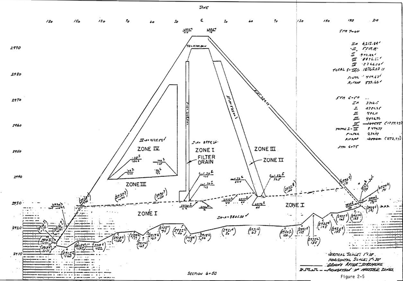
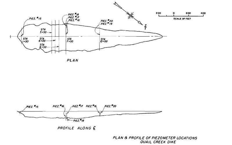
The Quail Creek Dike was designed as a 1,980 foot long, 78 foot high zoned earthfill structure. The cross section would consist of a centrally located Zone I, low permeability, core with a 10 foot thick, low permeability Zone II liner along the upstream face of the Zone I core. Downstream of the core was a 4 foot thick vertical sand filter. The upstream shell was a Zone III, pit run material and the downstream shell consisted of a Zone IV, random fill surrounded by Zone III material. Eighteen inches of basalt riprap served as upstream erosion protection. Six piezometers were installed on the dike, extending into the embankment and foundation.
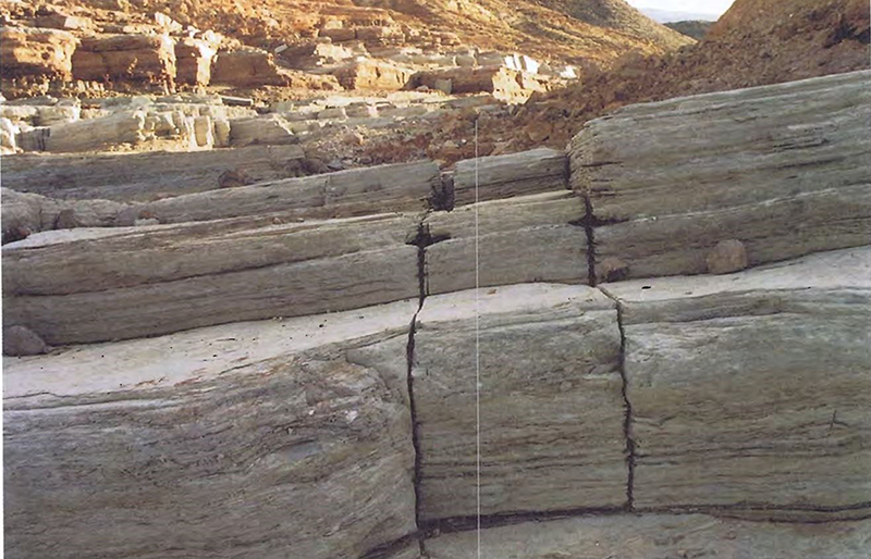
The original foundation investigation consisted of 10 vertical holes with minimal water losses in all but one indicating low permeability gypsiferous bedrock, below 10 feet of weathered bedrock. A permeable sandstone unit located in the left abutment was also identified. Based on the results of the foundation investigation a 30 foot wide cutoff with an average depth of 10 feet through weathered rock was included in the design. The design called for one foot of Zone II material to be placed on the bottom of the cutoff trench. Grouting in the sandstone section was also included as part of the design. Aside from brooming and air cleaning, no other treatment of the rock foundation was specified. During construction, because the rock foundation consisted of elongated ridges and valleys oriented perpendicular to the axis of the dam, it was decided to level the foundation using Zone I material. In some instances depth of Zone I material was more than 10 feet and extended from the upstream toe to the downstream toe resulting in a perched zoned embankment dam.
As the reservoir reached elevation 2924 feet, seepage along the left downstream toe of the dike became apparent and the owner began to measure and record the seepage rate. By the end of February 1986, the seepage flows had reached 5 cfs. Initial response to this increase was to place a sand and gravel filter blanket over the area where the seepage surfaced as well as installing 18 inclined drains along the downstream toe in March 1986.
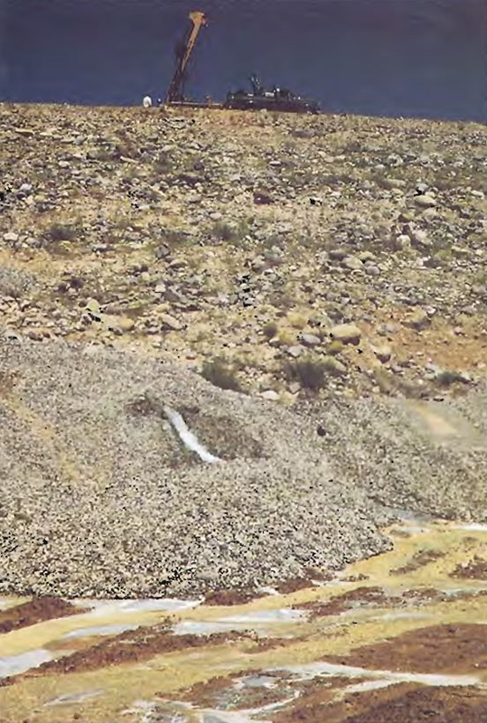
In April of that year, a contract for dike foundation grouting was awarded to Boyles Brothers and work began in May. Seepage at the time was estimated at 6.3 cfs with the reservoir elevation at 2969 feet. Grouting was accomplished by drilling through the embankment and injecting grout into the foundation with the use of casing to protect the embankment from hydraulic fracturing. During grouting in several locations the casing was pulled up into the embankment allowing grouting of the lower 7 to 15 feet of the embankment. This grouting identified several open conduits in the dike foundation. Several stages experienced large grout takes of more than 300 sacks of cement. The largest take during this grouting sequence was 805.5 sacks near the left abutment between stations 6+20 and 6+60 at depths of 7 to 12 feet into the foundation. This grouting sequence concluded in September 1986 with total seepage being reduced to 0.3 cfs at a reservoir level of 2949. In October, an upstream cutoff trench was constructed and a partial blanket installed at the upstream toe of the dike and extending 500 feet into the reservoir basin.

As the reservoir filled in June 1987, seepage at the downstream toe began to increase. Additionally, a two foot diameter sinkhole was discovered at the downstream toe on June 25th. A graded filter was installed over the area of the sinkhole and a second sequence of grouting was planned to begin in July. This grouting was similar to the first round with the exception that the reservoir level was at elevation 2970 feet, only 15 feet below the spillway crest. The focus was in the area of station 6+00. The contractor experienced several large grout takes during the second grouting campaign and also experienced seepage and grout exiting at the downstream toe during grouting operations. Grouting continued until April 1988 at which time seepage had been reduced to 1 cfs with the reservoir level at the spillway crest (2985 feet).
During the summer of 1988 as the reservoir was held at elevation 2984 feet, seepage continued to increase reaching 5 cfs by the end of August. Seepage was now mainly observed closer to the left abutment around station 4+30. In September, a third round of grouting was undertaken. As with the second campaign, the reservoir was not lowered to facilitate this grouting. On September 21, a major opening was identified near station 5+50. It was reported, “Heroic efforts were made to plug the conduit against substantial flow caused by the reservoir head.” Grouting in the hole continued for 10 days to no avail. In an effort to seal the hole conventional concrete was pumped into the hole. Sand and gravel from the initial five cubic yards manifest at the downstream toe 45 minutes after placement. With continuous concrete loads and using both concrete and grout the hole was finally sealed on October 14. In all 100 cubic yards of concrete; 2,356 sacks of cement; and large amounts of filler materials had been injected into an 8-foot stage of the drill hole near 5+50. Grouting continued until November 18, when seepage at the downstream toe had been reduced to 0.8 cfs with the reservoir at elevation 2976 feet. With the seepage apparently under control the owner began to fill the reservoir through the month of December.
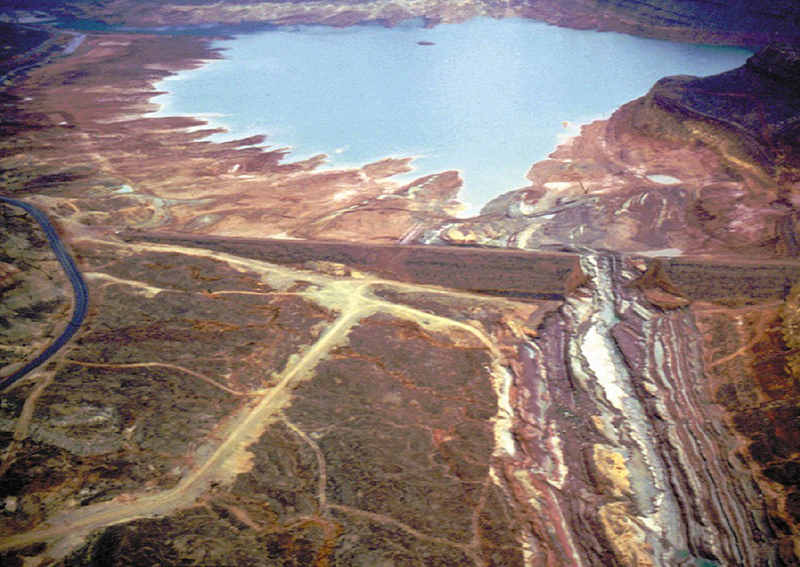
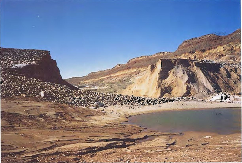
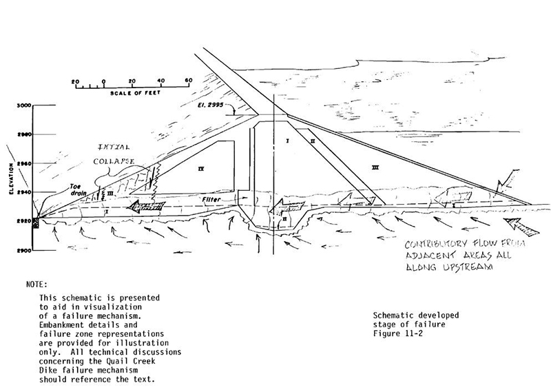
On the morning of December 31, 1988, cloudy seepage was observed at the downstream toe near station 5+90 near an observation well. Seepage flows were estimated at 200-300 gpm. Over the course of the day, equipment operators placed gravel over the ever-increasing area in an attempt to control seepage. Inspectors watched at the upstream edge for whirlpools, vortices, and other signs of seepage entrances to the foundation, but none were identified. As night fell a light plant was brought to the site and set up on the dike crest focusing illumination on the downstream toe. By 10:30 PM, the seepage flow rate had reached 70 cfs and the flow direction had changed from vertical to horizontal with a growing hole at the downstream toe. Unable to control the flow, personnel and equipment were moved to safe locations and a downstream evacuation was ordered. Between 11:00 and 11:30 PM, a wedge 50 feet wide and 25 feet high suddenly dropped several feet, blocking flow temporarily until flow resumed and began removing the collapsed material. Erosion continued toward the reservoir until at 12:30 AM on January 1, 1989, Quail Creek Dike failed, releasing an estimated 25,000 acre-feet of water into the Virgin River and downstream flood plain; the result of a breach 300 feet wide and some 80 to 90 feet deep.
Several downstream bridges and roads were damaged or washed out completely. Fields were flooded destroying crops, equipment and livestock. Some 30 homes and 58 apartments sustained damage due to the flood. No loss of human life was reported thanks to the evacuation efforts of emergency responders. Damage from the breach was estimated at $12 million.
“The failure of Quail Creek Dike motivated the Utah legislature to enact stronger dam safety laws in the state.” - Dave Marble, State Dam Safety Engineer
In the aftermath of the failure, Utah Governor Norm Bangerter called for an independent review of the failure and events leading up to the failure. The primary conclusion reached by the review team was that failure had resulted from embankment materials being placed on the foundation without appropriate protection against seepage moving along the foundation contact. They further stated that, “if the materials had been protected by proper filters, drains, and foundation surface treatment, the failure would not have occurred. This is not a new lesson, but rather a lesson relearned and reinforced.”
The reviews also identified that the assumption during design that, “there would be very little seepage through the dike foundation below the shallow cutoff was not valid and had a profound effect on the design of seepage erosion protection.” Noteworthy to the author is that the investigation of the foundation consisted of 10 vertical holes. With the exception of one, all of the borings indicated low permeability bedrock. However, the vertical nature of the jointing in the foundation would be difficult to identify with small diameter vertical drill holes.
As a result of the failure, dam safety regulations in Utah were strengthened. A new roller-compacted concrete (RCC) dam was eventually built to replace the failed Quail Creek Dike.
References:
(1) James, Robert L. et. al. (1989). Investigation of the Cause of Quail Creek Dike Failure Report of Independent Review Team.
(2) Carlson, Darrell D., Meyer, David F. (1995). Flood on the Virgin River, January 1989, in Utah, Arizona, and Nevada. Water-Resources Investigations Report 94-4159.
(3) James, Robert L. et. al. (1989). Safety Evaluation of Quail Creek Dam.
(4) Washington County Historical Society. (2011). Quail Creek Dam & Reservoir.
This case study summary was peer-reviewed by Nathaniel Gee P.E., Tennessee Valley Authority.


Lessons Learned

Emergency Action Plans can save lives and must be updated, understood, and practiced regularly to be effective.
Learn more
High and significant hazard embankment dams should have internal filter and seepage collection systems.
Learn more
Intervention can stop or minimize consequences of a dam failure. Warning signs should not be ignored.
Learn more
Regular operation, maintenance, and inspection of dams is important to the early detection and prevention of dam failure.
Learn more
Stability of the dam foundation and other geologic features must be considered during dam design.
Learn more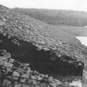
The first filling of a reservoir should be planned, controlled, and monitored.
Learn more
Timely warning and rapid public response are critical to saving lives during a dam emergency.
Learn moreAdditional Lessons Learned (Not Yet Developed)
- High and Significant Hazard Embankment Dams Should Have Internal Filter and Seepage Collection Systems.
- Proper foundation cleaning and treatment is critical to the construction and performance of dams.

Design Standards No. 13: Embankment Dams - Chapter 5

Filters for Embankment Dams

National Engineering Handbook Part 633 Chapter 26