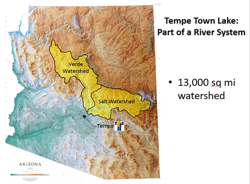
Historically, the Salt River was a perennial source of water to the early residents of the Phoenix Valley. With a drainage area of nearly 13,000 square miles, the river provided many benefits to the area including water for irrigation and recreation during the very hot summer months. However, the river also proved to be an unpredictable flooding hazard, and would periodically experience major floods that washed out roads and bridges, including the railroad bridge in the late 1800’s and Mill Avenue Bridge in the 1990’s. Beginning in the early 1900’s, the large watershed upstream of the City of Tempe began to be regulated with the construction of Granite Reef Diversion Dam (1908), Roosevelt Dam (1911), Mormon Flat Dam (1925), Horse Mesa Dam (1927), Stewart Mountain Dam, (1930), Bartlett Dam (1939) and Horseshoe Dam (1946). This regulation gradually shifted the river dynamics and transformed the Salt River into the ephemeral river that exists today. What was once a year-round source of water is now a dry river bed that only experiences flow when large floods occur that cannot be fully contained by the upstream reservoirs or when significant runoff occurs in unregulated sub-watersheds like the Indian Bend Wash.
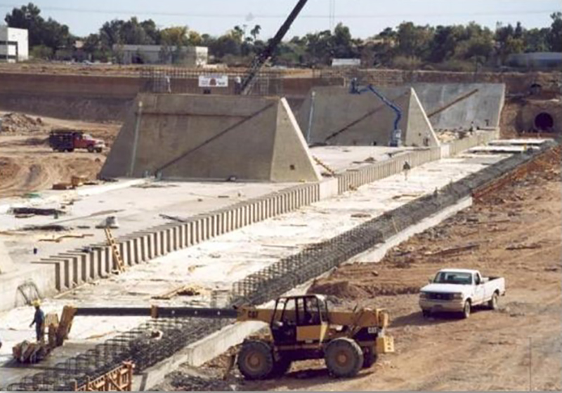
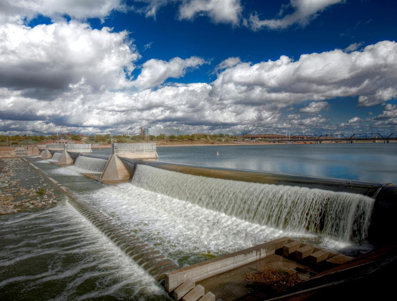
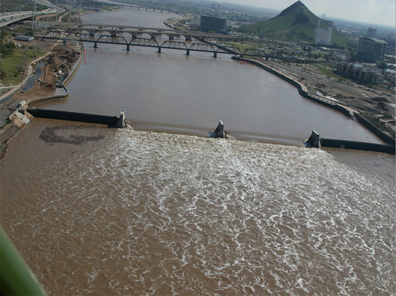
With this change in river dynamics came a shift in land use. Rather than being a place for refuge and recreation, the dry river bed began to attract landfills, quarry mining, and other industrial businesses. What had once been a place of gathering became an eyesore for the community. As early as 1966, community leaders had a vision to redevelop the riverbed and recapture some of what the original Salt River provided (RSAF, 2019). Tempe Town Lake Dam was the crowning jewel of this vision. Constructed from 1997 to 1999, Tempe Town Lake was impounded by two inflatable rubber dams (one on the upstream side of the reservoir, and one on the downstream side). These rubber dams were designed to be deflated and allow flood water to pass unabated without increasing flood elevations upstream of the dam. The bladders could then be re-inflated to capture the tail end of the flood, thereby creating a recreational lake in the middle of the Arizona desert. The result was a 220-acre urban lake that quickly became a centerpiece for economic development, community events and recreation. With the addition of a beach, outdoor walkways, concert facilities, a marina and more, the lake soon garnered the claim of being the 2nd most visited attraction in Arizona (behind only the Grand Canyon).

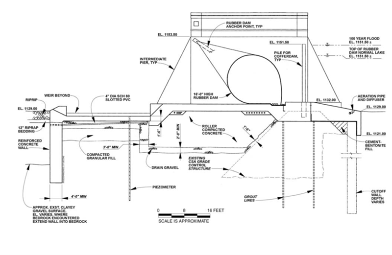
The downstream dam consisted of four 16-foot-high and 200-foot-long air-inflated rubber bladders. Due to percieved susceptibility of the rubber bladders to vandalism, ceramic chips were embedded on the dry side of each rubber bladder to help prevent piercing or slicing of the rubber portion of the dam. The bladders were anchored to a roller-compacted concrete (RCC) foundation. The dam also included a reinforced concrete cutoff wall downstream of a stilling basin and three reinforced concrete piers that anchored the end points of the rubber bladders. The dam was constructed on top of an existing grade control structure. Foundation treatment included grouting and construction of an upstream cutoff wall.
One important feature of the dam was an innovative water capture and recycling system incorporated into the stilling basin design. In order to protect the rubber bladders from the intense heat of the desert sun (sometimes reaching 150°F at the ground surface), water was allowed to flow over the bladders continuously. This water was then captured in the stilling basin and pumped back into the lake to provide a cooling system with minimal water loss. Unfortunately, this unique system did not function as intended. The rubber bladders sagged at the middle which did not allow for distribution of flow over the entire bladder. As part of the regular dam inspection process, it was found that the rubber bladders were deteriorating more quickly than anticipated as a result of exposure to extreme heat. In 2007, the bladder manufacturer evaluated the condition of the rubber dams and recommended replacing the bladders after 10 years of service.
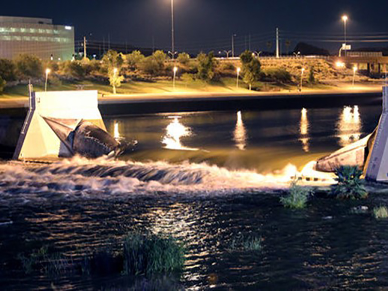
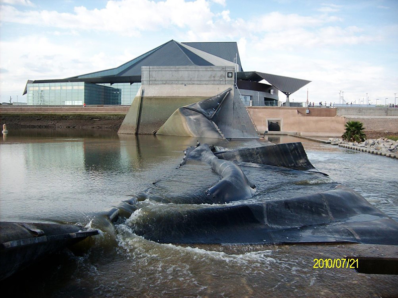
The bladder replacement was scheduled to occur in early 2010. This was delayed to July 2010, however, due to above normal precipitation and spring runoff within the Salt River channel. At 9:44 PM on July 20, 2010, less than 12 hours before construction crews were scheduled to begin work on replacing the bladders, Bladder No. 2 at the downstream dam burst and immediately deflated. Water poured out into the empty river bottom, and the lake was essentially drained by noon the next day. Fortunately, there was no loss of life or downstream property damage since the resultant flood was contained entirely within the banks of the Salt River. The failure received national media attention where unfounded speculation was made that the failure resulted from sabotage or terrorist activity (Brady & Sabol, 2011).

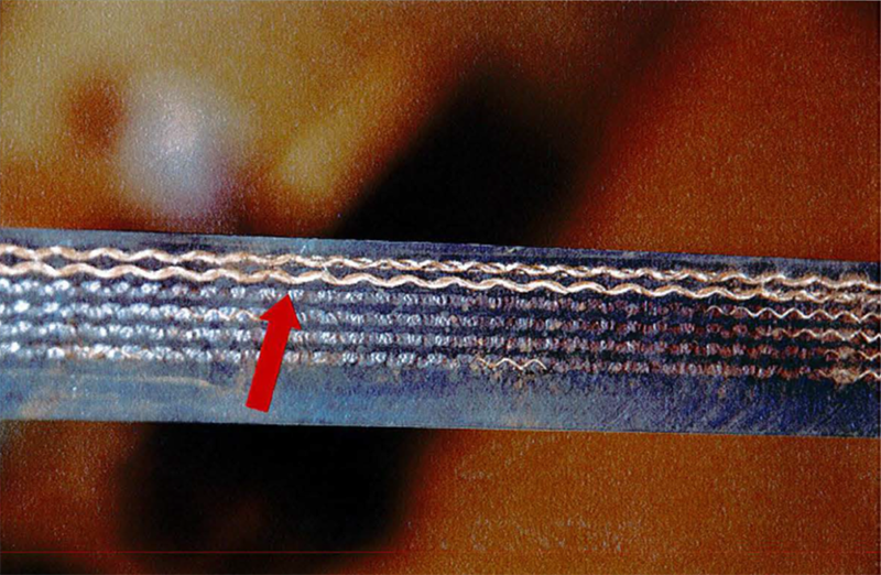
A forensic investigation performed by SEA, Ltd. attributed the failure to weakening and separation of the rubber bladder layers due to a combination of the age of the dam and the environmental conditions in which it existed. The delamination or separation of the layers of reinforced rubber that comprise the rubber bladder is characteristic of Intra Carcass Pressurization (ICP). The rupture occurred at the bottom of the bladder where it made contact with the concrete apron. Repetitive flexure occurred at this point on the bladder due to a back and forth motion of the bladder in response to the force of the water against the dam. The flexure is believed to have caused small internal tears which then became the accumulation location for air that penetrated the reinforced rubber bladder. The process of ICP was accelerated by the high temperatures the structure was subjected to. Over time, air penetrated and built up pressure within the bladder wall, causing further delamination and reducing the strength of the bladder wall until it ruptured (SEA, Ltd., 2010).
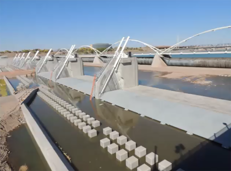
After the failure, all four downstream rubber bladders were replaced as previously scheduled. The replacement bladders were provided by the bladder manufacturer under a five-year lease agreement to the City of Tempe with a condition that they be permanently replaced by the end of the leasing term. By that time, the bladder manufacturer had discontinued sales of their rubber dams. Concurrent with the bladder replacement, a new pedestrian bridge was installed on top of the piers that held the bladders in place (AZFamily, 2011). The pedestrian bridge design included sprayers that were intended to keep the new bladders cooled until their eventual replacement. Ultimately, the rubber dam was replaced with a hydraulically operated steel gate dam located approximately 200 feet downstream of the original rubber dam structure. Construction of the replacement structure was started in 2014 and completed in 2016.
In addition to the physical conditions that led to failure of the dam, several other lessons can be gleaned from this experience relating to design and assessment of hydraulic structures:
- Dam designers and inspectors should understand the vulnerabilities of the specific technologies or materials that are being employed. There may be unique potential failure modes that need to be addressed or considered as well as site-specific environmental factors (e.g. extreme heat and repetitive wave motion as was the case here, but also potential for ice loading, rigorous operational conditions, debris loading or clogging, etc.). For materials that are critical to the performance of a dam, non-destructive evaluation or inspection techniques should be identified and regularly applied as part of an Operation and Maintenance Plan. This plan should also include guidance on when action is needed to address unexpected or accelerated material degradation.
- Dam designers and inspectors need to understand the value of “non-critical” mechanical and/or operational features of a facility. In the case of Tempe Town Lake Dam, the dysfunction of the cooling system accelerated or even led to deterioration and failure of the rubber bladder. The dam could operate without this cooling system and did so successfully for several years. However, while the cooling system was not critical to the ability to impound water, it was vital to the long-term maintenance and integrity of the structure. Mechanical and electrical features related to operation, maintenance, monitoring and/or instrumentation should not be overlooked in designing and inspecting dams. If it is found that these features are inoperable or not operating as intended, action should be taken to address the deficiency.
- Dam failures often occur due to a series of events over a prolonged period of time and can be contributed to or initiated by seemingly small or inconsequential events. The hot Arizona sun and mild rocking action of the bladders worked away for more than a decade prior to failure of the dam. This progression of failure is not uncommon. In fact, dam failures are often preceded by complex interactions of both physical and human factors that begin years or decades prior to the failure (Alvi, 2020). Since these events advance slowly and even imperceptibly, it is sometimes difficult to observe their progression through periodic dam safety inspections. In assessing risk, it is also sometimes difficult to foresee the initiating event of these types of potential failure modes.
- Even the best laid plans can’t eliminate all risk of failure. The need to provide cooling of the rubber bladders was identified and addressed during the design of Tempe Town Lake Dam. Regular inspections and assessments of the integrity of the structure were performed. When a problem was identified, a plan was put in place to replace the deteriorated bladders. Unfortunately in this case, all of these plans and efforts came just short of preventing failure. There is risk inherent to all dams and levees that can be mitigated but not entirely eliminated.
References:
(1) RSAF. (2019). Still Image. Rio Salado & Tempe Town Lake Website. Rio Salado Architecture Foundation.
(2) Holand, C. (2011). Tempe Town Lake Pedestrian Bridge Opens to Walker, Runners, Cyclists. Arizona's Family.
(7) Durkee, D., Ackerman, A. & Schweiger, P. (2013). Reviewing refurbishment options for Tempe Town Lake Dam, Arizona. Hydropower & Dams, 4.
This case study summary was peer-reviewed by Chris Kabala, P.E. (City of Tempe) and Stewart Vaghti, P.E., CFM (GFT).


Lessons Learned

Dam incidents and failures can fundamentally be attributed to human factors.
Learn more
Intervention can stop or minimize consequences of a dam failure. Warning signs should not be ignored.
Learn more
Regular operation, maintenance, and inspection of dams is important to the early detection and prevention of dam failure.
Learn more
Site security is a critical aspect of dam safety that shouldn't be overlooked or disregarded.
Learn moreAdditional Lessons Learned (Not Yet Developed)
- Dam designers and inspectors should understand the vulnerabilities of the specific technologies or materials that are being employed.
- Dam designers and inspectors need to understand the value of “non-critical” mechanical and/or operational features of a facility.
- Dam failures often occur due to a series of events over a prolonged period of time and can be contributed to or initiated by seemingly small or inconsequential events.
- Even the best laid plans can’t eliminate all risk of failure.

It is a New Dam, How Can It Fail? – FMEA for Design of New Tempe Town Lake Dam

Reviewing Refurbishment Options for Tempe Town Lake Dam, Arizona

Tempe Town Lake Dam: Another Burst Bubble


Tempe Town Lake Project Rubber Dam Design/Construction/Operation/Repair