Failure of high and significant hazard dams may result in loss of life, significant property damage, or both. Because of these consequences, a 2-stage filter and drain system is a critical design feature for embankment dams. A filter and drain system is used to capture and measure seepage, protect against backward erosion (piping) and erosion through cracks, and protect against internal erosion due to seismic events.
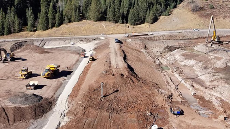
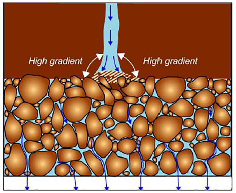
A 2-stage filter and drain system in embankment dam design and construction refers to zones of specifically designed, granular materials included as a means of capturing, controlling, and directing seepage flows. The purpose of the filter and drain system is threefold: 1) Relieve hydraulic gradients within the dam, 2) Prevent the movement of soil particles, and 3) Serve as a self-healing zone to arrest seepage erosion through cracks.
There are several publications documenting how to design a proper filter and drain system. Several federal agencies including the Natural Resources Conservation Service (NRCS) and the Bureau of Reclamation (USBR) have developed standards for filter and drain design. These procedures were developed largely from studies conducted by the NRCS in the 1980’s.

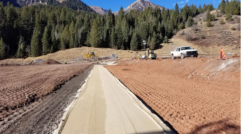
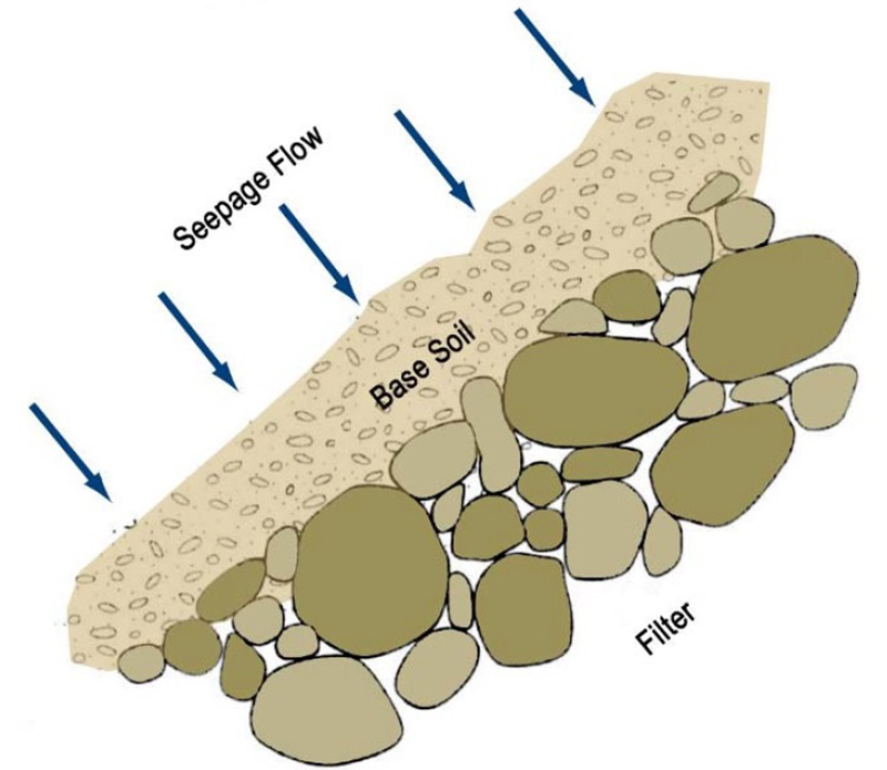
Filter zones are constructed of finer grained, granular materials (i.e. clean sand) with a defined gradation. The requirements of the filter material are determined by analyzing the gradation of the soil to be protected by the filter; referred to as the base soil. The granular material provides openings that are small enough to prevent the migration of base soil particles while allowing seepage water to pass through the filter. Filter design results in the development of a gradation band used to evaluate proposed filter materials. Filters are generally made of engineered sands produced by crushing, screening, and washing. Filters are designed to be self-healing meaning the granular material will not sustain a crack.
Drains and collection pipes are generally included with the design of filters. Drain zones are constructed of granular materials that are coarser than the filter. Gradation bands for drain materials are developed through the same procedure used for the design of the filter. The coarser drain allows for the rapid movement of seepage to a collection pipe network. The collection pipe network is generally composed of slotted or perforated pipe and solid pipe. The size of the slots or perforations are determined in conjunction with the design of the filter and drain to prevent movement of those materials into the collection pipe.
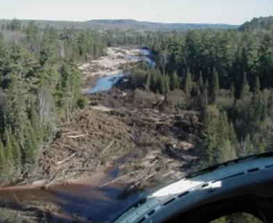
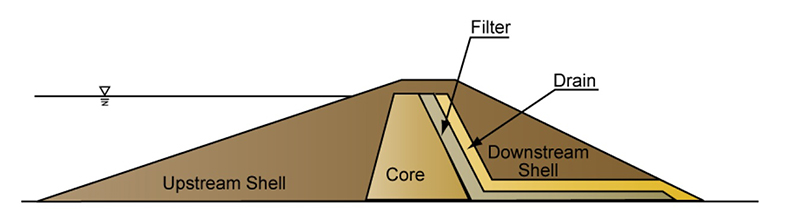
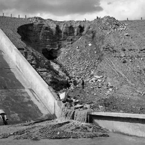
A 2-stage filter and drain system is the principal defensive design measure to protect against piping and internal erosion. One of the more commonly discussed failure mechanisms for embankment dams is backward erosion or piping. Backward erosion occurs when hydraulic gradients are sufficiently high to begin moving soil material near a seepage exit point. As soil is removed the gradient increases leading to continued erosion possibly at an increasing rate. This erosion may continue over time, eventually leading to a complete failure of the dam. Filter and drain zones are generally placed downstream of a fined-grained core in embankment dam design. Seepage water passing through the core encounters the filter and drain zones that relieve pore water pressure by providing a free draining exit while preventing movement of the core material into the filter and drain materials, the downstream shell or foundation materials.
Even under the most ideal construction circumstances, embankment dams are prone to cracking due to settlement, soil stress relief (bridging), or seismic events. This cracking can create concentrated seepage that can lead to scour of the crack and continued erosion through the crack. Filters are designed to be self-healing and will not sustain a crack. Placed downstream of the core and any crack in the core, filters prevent eroded material from passing through them. As the finer-grained soil becomes trapped on the filter it creates what has been termed a “filter-cake”. This filter-cake prevents the continued erosion of fine-grained material, effectively sealing the crack.
Filter and drain zones should be designed and built of sufficient width to remain intact even after deformation caused by seismic events considered during design. Providing for this allows the filter to continue to function after the design seismic event, preventing internal erosion through cracks created during the event and failure of the embankment dam.
Because the failure of high and significant hazard dams may result in the loss of life and/or significant property damage, defensive design measures should be considered to reduce the possibility of failure. For embankment dams, a 2-stage filter and drain system provides an indispensable line of defense against internal erosion and piping failure mechanisms. Filters and drains reduce hydraulic gradients while preventing movement of soil particles. They prevent erosion through cracks developed during construction or caused by seismic events and they provide a controlled way of collecting, measuring, and monitoring seepage through embankment dams. Because of the benefits they provide, the use of filter and drain systems should be considered fundamental in the design and construction of high and significant hazard embankment dams.
References:
This lesson learned was peer-reviewed by David Marble, P.E., Utah Division of Water Rights.

")
")

Anita Dam (Montana, 1997)

Baldwin Hills Dam (California, 1963)

Big Bay Lake Dam (Mississippi, 2004)

El Guapo Dam (Venezuela, 1999)
Fontenelle Dam (Wyoming, 1965)

Lawn Lake Dam (Colorado, 1982)

Little Deer Creek (Utah, 1963)

Penn Forest Dam (Pennsylvania, 1994)

Prospect Dam (Colorado, 1980)

Quail Creek Dike (Utah, 1989)

Teton Dam (Idaho, 1976)

Williamsburg Reservoir Dam (Massachusetts, 1874)

Earth Dams and Reservoirs (TR-60)

Filters for Embankment Dams: Best Practices for Design and Construction

Chimney Filter/Drain Design and Construction Considerations

Design Standards No. 13: Embankment Dams - Chapter 5


National Engineering Handbook Part 633 Chapter 26