Dam Description
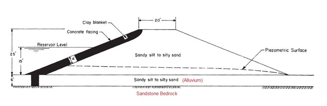
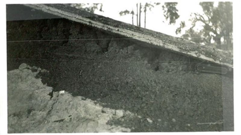
Sheffield Dam was built in late 1917 in a ravine referred to as Sycamore Canyon, north of the city of Santa Barbara, California. Constructed as a distribution reservoir for the Santa Barbara Municipal Water Department, the dam was named after Eugene Sheffield, one of the city’s first water commissioners. Original plans and specifications for the dam were prepared in the engineering offices of Mr. J.B. Lippincott, of Los Angeles, California [12]. The dam was capable of impounding 45,000,000 gallons, or roughly 138 acre-feet. Sheffield Dam had a maximum height of 25 feet and was approximately 720 feet long, although at least one account lists the dam length as 800 feet [6]. The embankment was constructed of material excavated from the reservoir and compacted by routing light construction equipment over the fill. Nunn (1925) reported that the dam “had been carefully constructed by puddling, and every precaution taken to insure safe construction” [6]. Explorations conducted by the U.S. Army Corps of Engineers (USACE) in 1949 indicate that the embankment fill was composed primarily of silt sand and sandy silt with cobbles and large boulders. No records are available with respect to the degree of compaction, although laboratory testing completed in the 1949 USACE study suggest a relative compaction of 35- to 40-percent [12]. The upstream slope was designed with a 4-foot-thick clay blanket which extended into the upstream toe up to 10 feet deep to serve as a cut-off wall. The clay blanket was overlain with a thin concrete facing, estimated to be 3 to 5 inches thick. The foundation consisted of a layer of terrace alluvium, 4 to 10 feet thick, overlying sandstone bedrock. USACE (1949) showed the alluvium to consist mainly of silty sand and sandy silt containing cobbles varying from 3 to 6 inches in diameter, with some thin layers of clayey sand and gravelly sandy clay. The upper 1 to 1.5 feet of foundation soil was observed to be somewhat looser than the underlying deposits. As reported by Huber (1927), “When the original dam was constructed, little, if any, top soil was removed” [3]. Seed et al (1968, 1969) similarly concluded that “there was no formal stripping of the upper soil layers prior to construction of the embankment” [9, 10]. Prior to the earthquake, observers indicated that considerable seepage was noted “both at the toe of the downstream slope and in the area below the toe ” [12]. Examination of the dam after the failure indicated that no leakage had occurred through the upstream core, but that seepage around and underneath the cutoff had saturated the lower part of the main structure.
Earthquake
On June 29, 1925, at roughly 6:42 am, a large earthquake occurred in the vicinity of Santa Barbara. The main shock had an estimated Richter magnitude of ML = 6.3 based on observed damage (note that other sources provide an estimated moment magnitude, MW, of 6.5 to 6.8 [2]). No strong motion instruments were in existence at the time. However, Willis (1925) inspected the damage in the city and assigned a maximum intensity of X (“Extremely high intensity tremor”) on the Rossi-Forel scale (see [5] for comparison to Modified Mercalli scale). Shaking was estimated to last 15 to 18 seconds, and six aftershocks were reported within 20 minutes of the initial shock [6]. Around 3:30 am, City Manager Herbert Nunn reported that he “was awakened by a strong odor of crude oil” [6]; a pressure gauge record for the City’s water department shows a slight tremor occurred around 3:27 am, likely a foreshock to the main event later that morning. During inspections conducted in November 1925, some four months after the quake, Byerly (1925) observed damage and assigned a Rossi-Forel intensity rating to each town he visited. Based on these data, Seed et al (1968) assigned an interpolated intensity at the dam site between VIII and IX, indicating a maximum ground acceleration of 0.15g based on empirical correlations available at the time of the study. Note that USSD (2000) provides an updated ground acceleration estimate of 0.25g based on more recent attenuation relationships [14]. Furthermore, Seed et al (1969) estimated a predominant frequency of three Hz at the ground surface of the dam site based on comparisons to similar earthquakes [10]. Within the city, the earthquake resulted in widespread damage, with up to 85-percent of commercial buildings destroyed in the downtown area. The city’s gas and electricity were shut off quickly after the quake, preventing further widespread destruction. In total, 13 deaths were attributed to the quake, though none occurred as a result of the dam failure.
Dam Failure
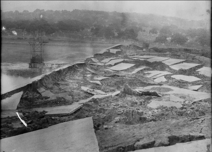
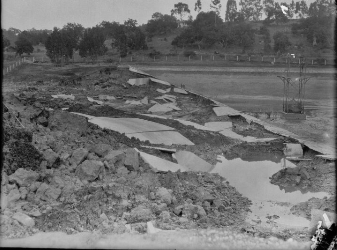
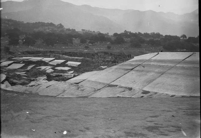
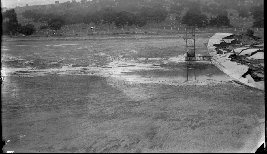
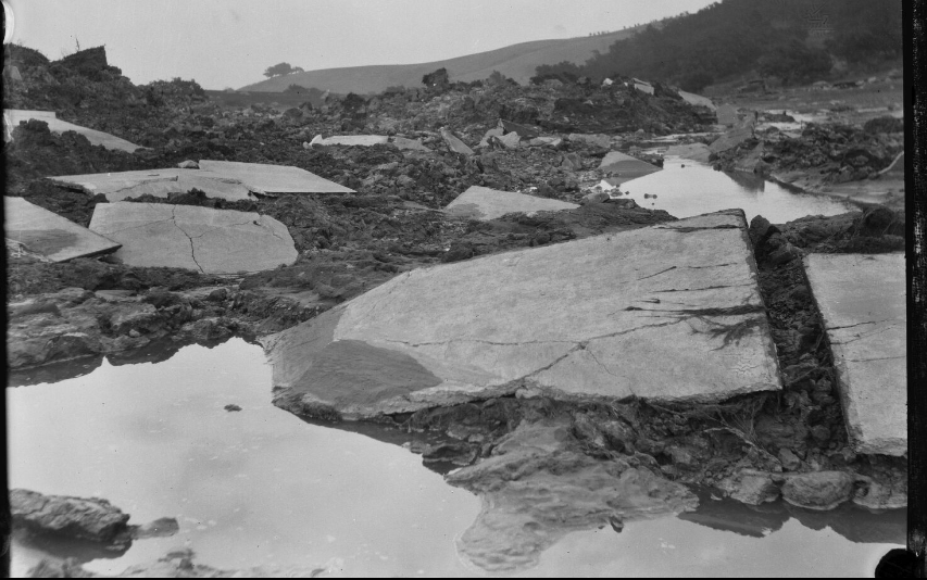
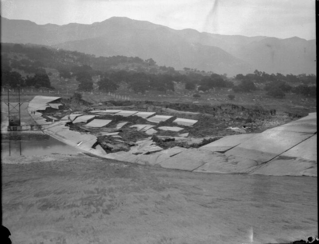
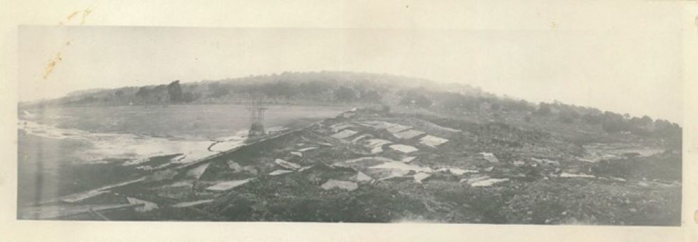
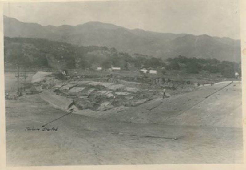
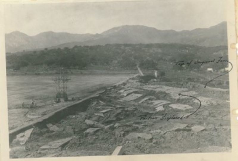
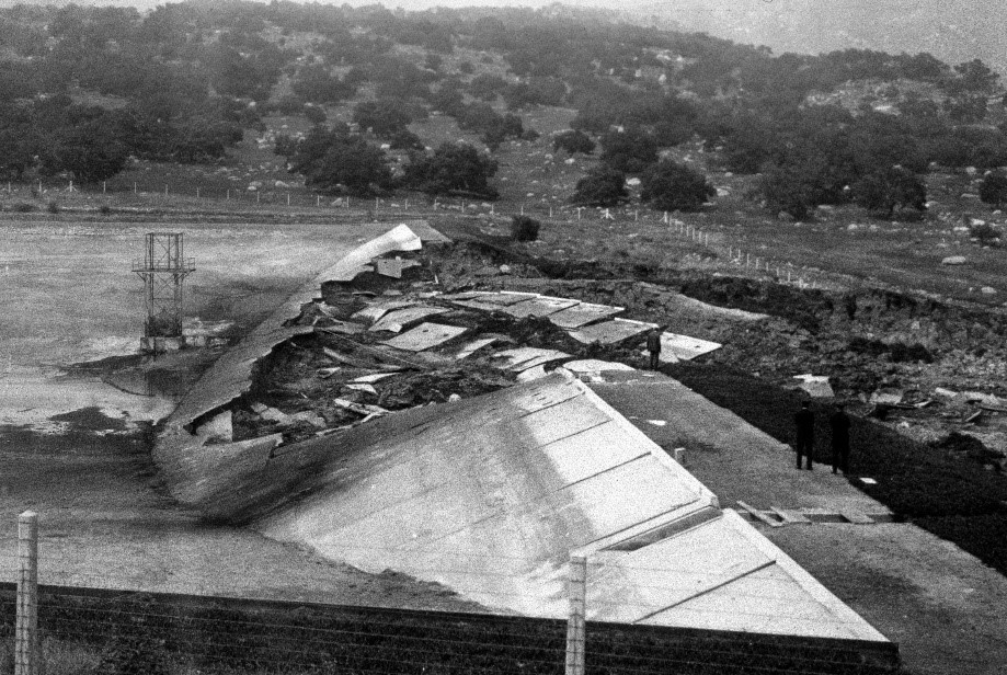
At the time of the earthquake, Sheffield Dam was partially full, impounding roughly 15- to 18-feet of storage. The strong shaking caused the dam to fail catastrophically downstream, releasing approximately 30,000,000 gallons, or about 92 acre-feet. The resulting flood wave “passed through the streets and into certain houses but it had so spread out that no loss of life resulted and the property damage was not serious” [3]. Estimated flood depths in the lower part of the city were 1 to 2 feet.
The song “Santa Barbara Earthquake” was written and recorded by Vernon Dalhart in July 1925. Released by Columbia, the record sought to capitalize on the widespread interest in the disaster.
There were no eyewitnesses to the dam failure. Observing the dam after the failure, Mr. M.M. O’Shaughnessy (1925) reported that “…a great mass of the center, about 300 ft. in length, slid downstream perhaps 100 ft.” Mr. V.E. Trace, Superintendent of the city’s Water Department, contended that “the failure of the original dam was due to not having a drainage system underneath the dam, consequently the bottom of the fill became saturated and in the movement of the earth below caused the sliding of a portion of the dam” [11]. This conclusion was supported by Willis (1925), who noted that the “foundations of the dam had become saturated by percolation, and the rise of the water as the ground was shaken formed a liquid layer of mud under the dam, on which it floated out, swinging about as if on a hinge” [15]. In his own account of the 1925 earthquake, Nunn (1925) commented that, “After examination by several prominent engineers, the conclusion has been reached that the base of the dam had become saturated, and that the shock of the earthquake, which was very heavy in this district, had opened vertical fissures from base to top; the water rushing through these fissures simply floated the dam out in sections” [6]. Discussing plans to rebuild the dam, Huber (1927) concluded that “Evidence gathered at the time pointed to the failure being due to lack of drainage under the dam, saturation and improper preparation of the sub-grade” [3]. From these accounts, Seed et al (1968) concluded that “sliding occurred on a surface near the base of the embankment, causing a large portion of the dam to move a considerable distance downstream, breaking up as it did so” [9]. As discussed below, the sliding failure was judged to be “related in some manner to a severe reduction in soil strength resulting from increases in pore-water pressure induced by the earthquake shaking” [9].
Repair and Reconstruction
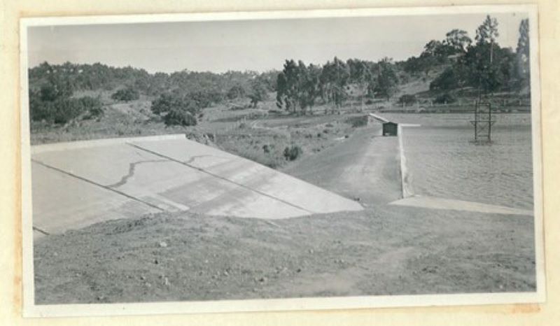
In 1925, a temporary structure was constructed to El. 647, or 11 feet lower than the original dam. The foundation for the temporary dam was stripped to bedrock and replaced with a well-compacted fill. Portions of the abutments of the original dam were left in place. In 1936, the dam was rebuilt to its original capacity, at which time the Sheffield Filtration Plant was also constructed to treat drinking water. Both the 1936 dam reconstruction and new filter plant were Public Works Administration projects.
Investigations and Root Causes
In a report published in June 1949, the USACE presented the findings of a field and laboratory study of the failure of Sheffield Dam. The study was undertaken to determine if the failure of Sheffield Dam was the result of a flow slide. Field exploration included five, 16-inch diameter auger holes advanced in the reconstructed dam (1936) and in the valley below the dam, where similar soil conditions were expected. Samples were collected to determine material properties and strength parameters. Stability analyses were also conducted with the critical circle method and an earthquake acceleration of 0.1 g. USACE (1949) ruled out liquefaction of the embankment and foundation, concluding that the failure of the dam could not be attributed to a flow slide, but that it “appears more likely that failure occurred along a shear plane” between the embankment and the foundation. Removal of the porous topsoil under the embankment and inclusion of a downstream toe drain were identified as two factors that “would probably have obviated the undesirable features of the design” [12]. Seed et al (1968, 1969) revisited the 1925 Sheffield Dam failure, performing new laboratory testing and additional analyses to determine the cause(s) of the failure [9, 10]. Additional material samples were gathered from similar soils downstream of the dam site, and static and cyclic triaxial and simple shear tests were performed on remolded samples to supplement material properties and strength parameters determined in the 1949 USACE study. Based on the additional data, Seed et al (1969) estimated a dry density for the upper alluvium ranging from 90 to 101 pounds per cubic foot (pcf), corresponding to a relative density of approximately 35 to 40 percent. Saturated isotropically consolidated-undrained triaxial compression test (ICU-TCX) samples remolded to in-situ conditions of the alluvium yielded an effective friction angle, φ’, of 34.5 degrees, and estimated total stress parameters of cohesion, c, of 204-205 pounds per square foot (psf), and friction angle, φ, of 13 degrees. Revised material property and strength data were used to perform both conventional pseudo-static analyses and dynamic finite element analyses to more accurately model the observed performance of the dam. Based on this work, Seed et al (1968, 1969) concluded that the most appropriate method for capturing the observed performance was the use of dynamic analysis employing finite element techniques in conjunction with cyclic loading simple shear test data. It was ultimately determined that “sliding of the Sheffield Dam was due to a liquefaction failure of the loose saturated silty sand (i.e., alluvium) near the base of the embankment” [10]. As reported in USSD (2000), the work by Seed et al (1968, 1969) was “perhaps the first application of dynamic finite element analysis to investigate the response and behavior of embankments dams, and led to the development of procedures and evaluation methods” which quickly became the standard of practice for dam safety engineering and earthquake engineering design [13]. Their analysis of the Sheffield Dam failure “noted the need to allow for the progressive development of liquefaction” in order to adequately explain the failure mechanisms [14].
Present Day
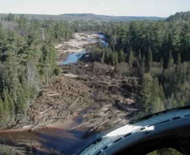
Sheffield Dam and Reservoir remained in operation until 2003, when the reservoir was decommissioned, and the site was transformed into a recreational park. The reservoir was replaced by two, buried 6.5-million-gallon concrete tanks. The location of the original (1936) earth embankment is now delineated by two rows of parallel boulders. Opened in 2004, the Sheffield Open Space is a scenic park owned and operated by the city of Santa Barbara.
References
(1) Byerly, P., 1925, “Notes on the Intensity of the Santa Barbara Earthquake between Santa Barbara and San Luis Obispo,” Bulletin of the Seismological Society of America, Vol. 15, No. 4, December, pp. 279-281. (2) Hough, S.E., and Martin, S.S., 2018, “A proposed rupture scenario for the 1925 Mw 6.5 Santa Barbara, California, earthquake”, Tectonophysics, Vol. 747-748, November 13, pp. 211-224. (3) Huber, W.L., 1927, Letter to Paul Bailey, State Engineer. August 10. Archives of California Department of Water Resources, Division of Safety of Dams. (4) Myers, D., 2014, “Decade Dam Failure Series: 90th Anniversary of the collapse of Sheffield Dam, CA” [Conference presentation and poster], Dam Safety 2014, Association of State Dam Safety Officials. (5) National Oceanic and Atmospheric Administration (NOAA), (n.d.), “Earthquake Intensity Database, 1638-1985,” National Centers for Environmental Information (formerly NGDC). (6) Nunn, H., 1925, “Municipal Problems of Santa Barbara,” Bulletin of the Seismological Society of America, Vol. 15, No. 4, December, pp. 308-319. (7) O’Shaughnessy, M.M., 1925, Letter to the Editor of the Engineering News Record, July 9. (8) Rogers, J.D., 2012, “Dams and Disasters: a brief overview of dam building triumphs and tragedies in California’s past” [presentation], California Colloquium on Water Lectures. (9) Seed, H.B., Lee, K.L., and Idriss, I.M., 1968, “An analysis of the Sheffield Dam Failure,” Report No. TE-68-2, Dept. of Civil Engineering, Institute of Transportation and Traffic Engineering, U.C. Berkeley, April. (10) Seed, H.B., Lee, K.L., and Idriss, I.M., 1969, “Analysis of Sheffield Dam Failure,” American Society of Civil Engineers, Journal of the Soil Mechanics and Foundations Division, Vol. 95, Issue 6, November, pp. 1453-1490. (11) Trace, V.E.., 1927, Letter to Paul Bailey, State Engineer. June 29. Archives of California Department of Water Resources, Division of Safety of Dams. (12) United States Army Corps of Engineers (USACE), 1949, “Report on Investigation of Failure of Sheffield Dam, Santa Barbara, California,” Civil Works Investigation, Flow Slide Phenomena, Office of the District Engineer, Los Angeles, California, June. (13) United States Committee on Large Dams (USSD), 2000, Observed Performance of Dams During Earthquakes, Volume II, pp. 147-151, October. (14) USSD, 2022, Analysis of Seismic Deformations of Embankment Dams, August. (15). Willis, B., 1925, “A Study of the Santa Barbara Earthquake of June 29, 1925,” Bulletin of the Seismological Society of America, Vol. 15, No. 4, December, pp. 255-278.
This case study summary was peer-reviewed by Alex Pires-Sturm P.E. (California Department of Water Resources – Division of Safety of Dams).


Lessons Learned

Dam failure sites offer an important opportunity for education and memorialization.
Learn more
Dam incidents and failures can fundamentally be attributed to human factors.
Learn more
Dams located in seismic areas should be evaluated for liquefaction, cracking, potential fault offsets, deformations, and settlement due to seismic loading.
Learn more
Earth and rockfill embankment dams must be stable under the full range of anticipated loading conditions.
Learn more
Stability of the dam foundation and other geologic features must be considered during dam design.
Learn more
Design Standards No. 13: Embankment Dams - Chapter 13