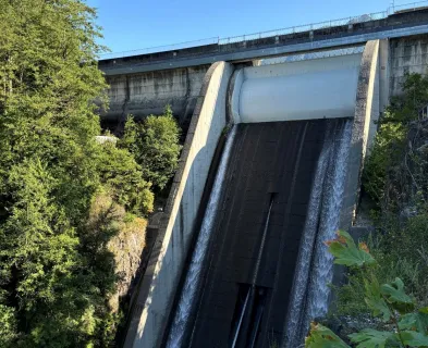
When a concrete dam impounds a body of water, it will experience a load or force commonly referred to as hydrostatic pressure. A variety of other forces such as uplift pressure, earth pressure, silt pressure, wave pressure, wind pressure, ice pressure, seismic acceleration, hydrodynamic pressure, and thermal stress from ambient temperature changes can also act on the dam depending upon site conditions. Though it is imperative to analyze all applicable force combinations specific to a given site when evaluating an existing gravity dam or designing a new one, history has proven that the consideration of uplift pressure is especially important.

Uplift is an active force that exists within both the foundation and the concrete structure itself. This pressure is present in cracks, pores, and joints of the concrete within a dam, at the interface between the dam and the foundation, and in cracks, pores, and seams within the foundation rock. Large uplift pressures can compromise the structural adequacy of concrete gravity dams and serve as the principal cause of failure. Because uplift pressures can greatly impact the stability of concrete gravity dams, they must be analyzed and accounted for during design and evaluation of such structures.
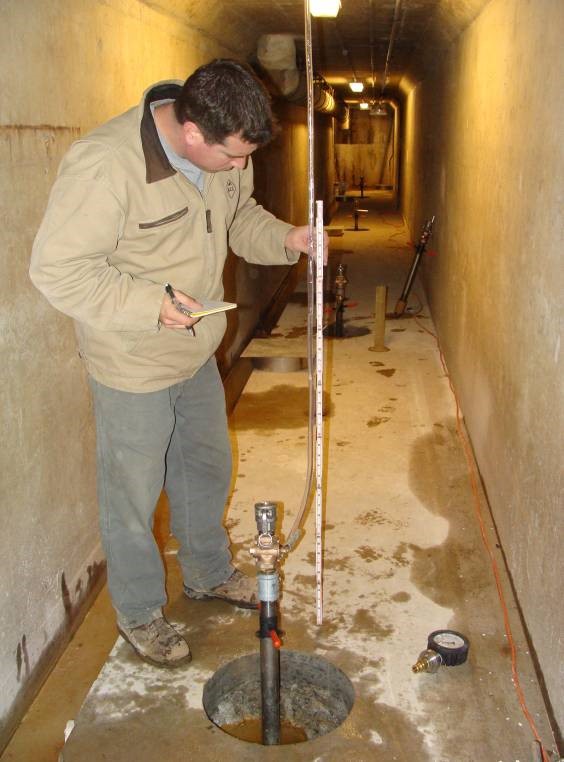
Direct reduction of uplift pressures can be accomplished by the incorporation of a drain curtain, also known as drainage or relief wells. These internal drainage systems consist of a series of vertical or vertically-inclined wells or boreholes that facilitate the draining of the foundation and abutments in order to relieve the uplift pressure caused by impounded water. Effectiveness in reducing uplift pressures through drainage systems is dependent upon drain hole size, depth, spacing, and maintenance as well as the character of the foundation. In addition, a grout curtain positioned upstream of a drain curtain within the dam’s base can also facilitate the reduction of uplift pressures by eliminating or decreasing the number of seepage paths.
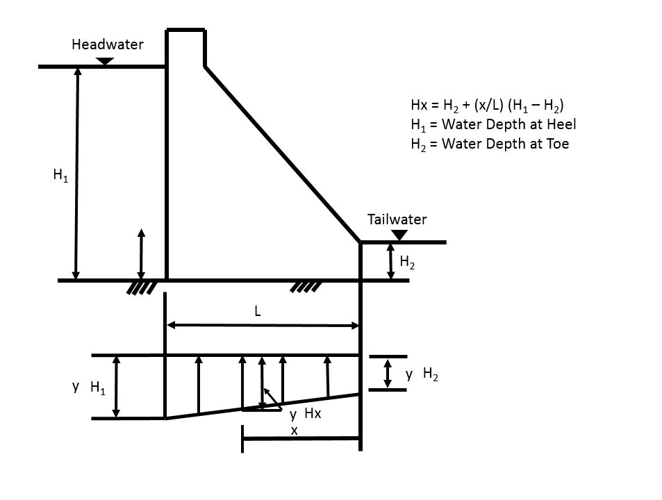
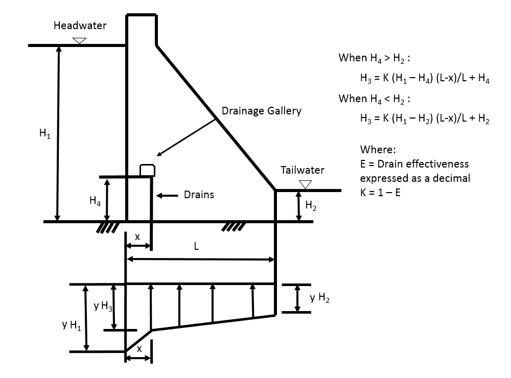
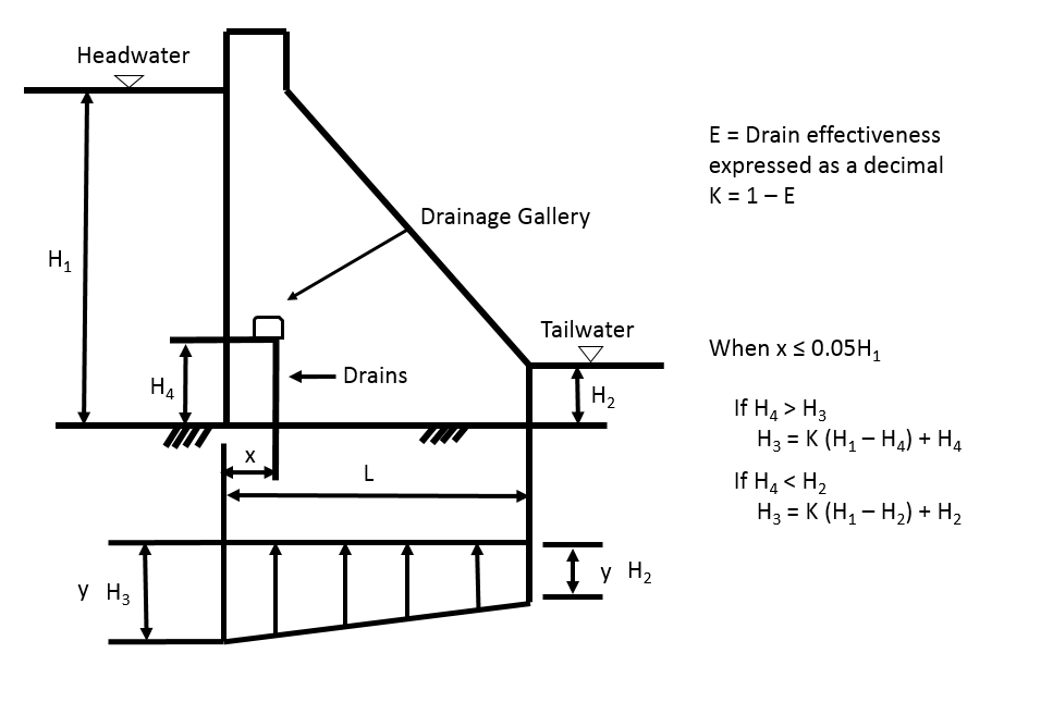
To address the potential for highly variable nature of foundation rock and concrete properties as well as construction quality within a given structure “the current design practice [for estimating uplift pressures in concrete gravity dams] relies heavily on simple empirical rules… [I]t is assumed that uplift pressure at the base of a dam without drains varies linearly from full reservoir pressure at the heel to tailwater at the toe. For dams with foundation drains, the pressure is assumed to follow a bi-linear tailwater plus some fraction of the difference between headwater and tailwater at the line of drains, to tailwater at the toe.” ¹
Prior to the 1920s, many gravity dams in the United States were designed without any allowance for uplift. The general view was that uplift could not develop at the base of a gravity dam to any significant degree since the dam by its own weight placed the structure in positive contact with its foundation. After some highly publicized dam failures in the early 1900s, engineers began to pay more attention to accounting for this force. At that time, the practice consisted of two components. The first component related to “uplift intensity” which assumed that uplift varied linearly from full reservoir pressure at the upstream face to zero or tailwater pressure at the downstream face. The second component related to the proportion of the horizontal area of the structure’s base or partial section above the base in which uplift acted upon. Depending upon foundation rock characteristics and whether or not grout and drain curtains were to be included, uplift intensity was applied to one-third, one-half, two-thirds, or the full horizontal base area. It wasn’t until the 1950s that engineers began to adopt the more conservative approach of applying uplift to the full base area regardless of whether or not grout and drain curtains were to be included. Since uplift can be a significant destabilizing force, any design or evaluation should properly account for it. In certain cases, it may be appropriate to install instrumentation to measure and confirm the validity of uplift assumptions.
References:
(2) FERC. (2002). Gravity Dams. Engineering Guidelines for the Evaluation of Hydropower Projects. Federal Energy Regulatory Commission.
(4) EPRI. (1992). Uplift Pressues, Shear Strengths, and Tensile Strengths for Stability Analysis of Concrete Gravity Dams, Volume I, EPRI TR-100345. Electric Power Research Institute.
(5) Houk, I.E. (1930). Uplift Pressure in Gravity Dams. Western Construction News, 344-349.


")
")

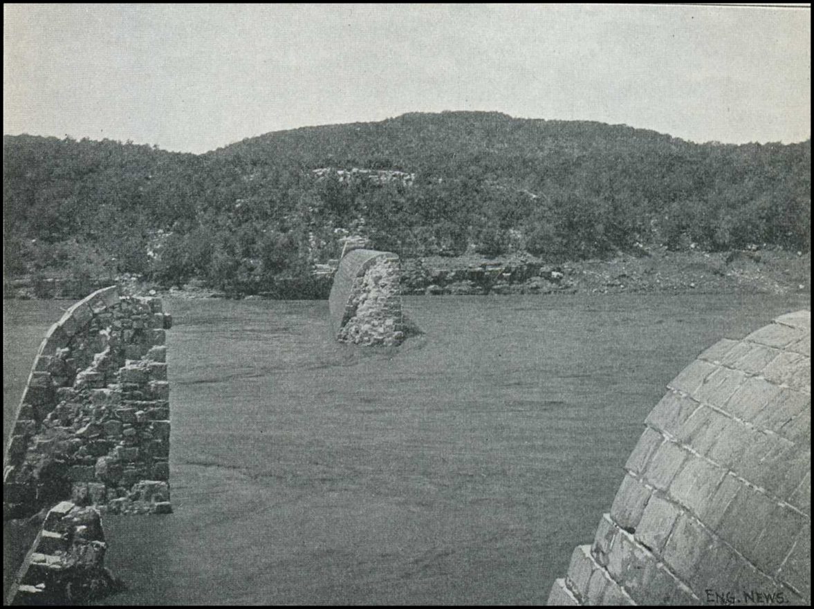
Austin (Bayless) Dam (Pennsylvania, 1911)

Camará Dam (Brazil, 2004)

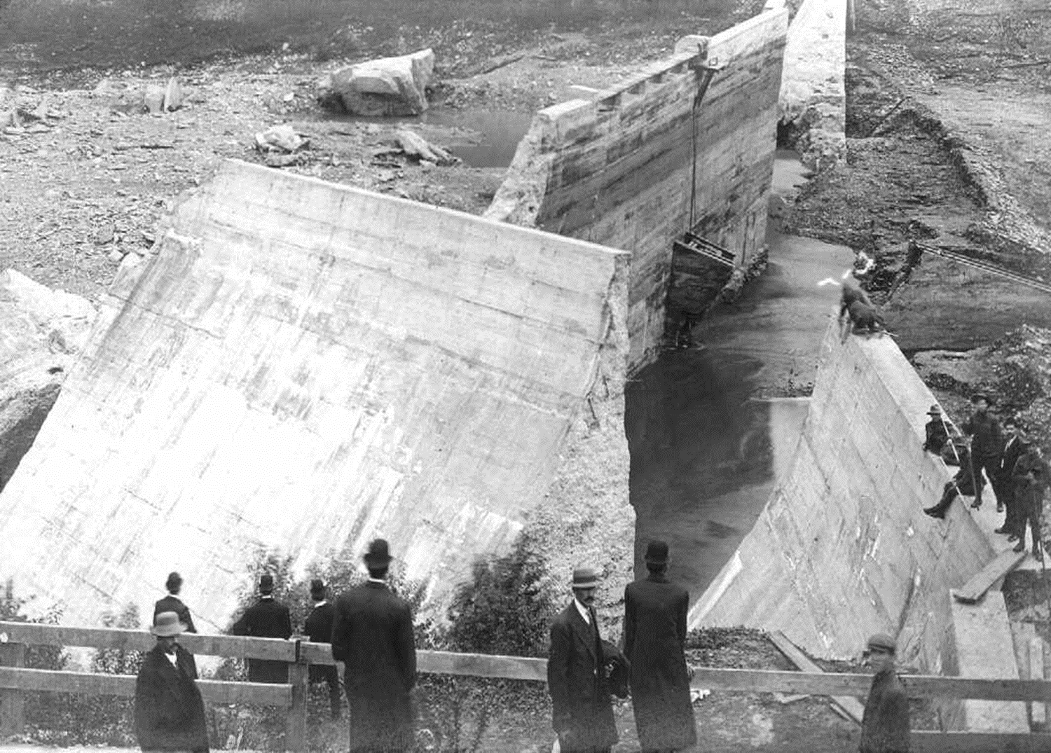
Malpasset Dam (France, 1959)

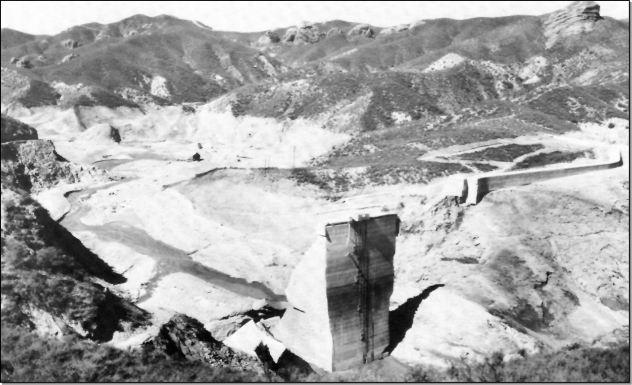
St. Francis Dam (California, 1928)
Design of Gravity Dams

Effect of Geology on Uplift and Dam Stability
Evaluation and Repair of Concrete Structures, EM 1110-2-2002
Gravity Dam Design, EM 1110-2-2200
It is a Crime to Design a Dam without Considering Upward Pressure: Engineers and Uplift, 1890-1930
On the Influence of Uplift Pressure in Concrete Gravity Dams
Risk Analysis for Concrete Gravity Structures
Stability Analysis of Concrete Structures, EM 1110-2-2100
Additional Resources Not Available for Download
- I.E. Houk. (1930). Uplift Pressure in Gravity Dams. Western Construction News, 344-349.
- EPRI. (1992). Uplift Pressues, Shear Strengths, and Tensile Strengths for Stability Analysis of Concrete Gravity Dams, Volume I, EPRI TR-100345. Electric Power Research Institute.